kamelryttarn:
Here are pictures of the stepper motor to confirm mine only has 4 wires.
Quite right - I need to get some better glasses - sorry. ![]()
kamelryttarn:
Here are pictures of the stepper motor to confirm mine only has 4 wires.
Quite right - I need to get some better glasses - sorry. ![]()
Hi,
Kamelryttarn, can I suggest you comment out the enable,LOW between the step changes.
Just change steps without pauses.
At the moment when you disable the driver you turn off all the outputs to the coils effectively adding dead time to the stepper motor.
The L298 will be able to handle the stepping and load.
This will probably increase your speed.
Tom.... ![]()
Thank you Tom! Yes I have thought about removing my delays between switching the outputs.
Another idea that just occurred to me: How about using an external voltage comparator and a voltage reference that compares the voltage over the shunt resistor and have it control the enable inputs? I think it MAY work co control the current when using lower speeds.
Has anyone tried this before?
Removed all unecessary delays and the switchin of the enable pins, but it doesn't work much better so I hooked it up to my borrowed logic analyser and saw something weird.
The high pulse on pin 8 is 2.07ms and the low pulse on the same pin is 2.28ms.
The high pulse on pin 9 is 2.06ms and the low pulse on the same pin is 2.29ms
The high pulse on pin 10 is 2.29ms and the low pulse on the same pin is 2.06ms
I believe this might have something to do with the fact that I feel I get better performance when I make use of the enable inputs and switch the pins during a small time frame when the outputs have been disabled.
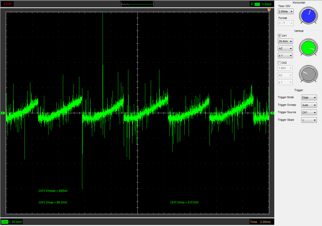
Here is a screenshot of the oscilloscope readings on the 20mOhm shunt resistor. It seem to be peaking at 80mV which would mean about 4A.
I made a lot of interesting observations yesterday when I hooked my circuit up to a variable power supply and was able to adjust the motor voltage as I was changing the speed with the potentiometer and also upload new code to my arduino.
I was able to get a fairly high speed from my little stepper and the L298 when I was pushing my power supply up to its maximum 24V, but things where starting to run a bit hot. I do not have any heatsink on my L298 so I decided to back of a bit when I couldn't keep my finger on it.
Driving a stepper at a large range of speeds with the L298 without any kind of voltage or current control seem more or less impossible. I could get high speed, but the current running through the driver and motor got way to high when I brought the speed down and adding delays where the motor was essentially not driven didn't help much. I noticed that for every speed setting there was a tight voltage window where the motor was running incredibly smooth, but when I went above or below that voltage the motor began to vibrate a bit. When running higher I assume the motor had time to stop and hold at each step before it was time for the next step.
I have learned a lot about steppers these last few days, and I think I will probably try another driver and see how it compares to the L298. I still think L298 is a very good choice for steppers with the arduino. It is easy to understand what is going on, and the current sens pins makes it very easy for those who are interested to hook up a shunt resistor to a scope and monitor what is going on with the motor coils. I used a USB oscilloscope and had some ground issues that account for most of the noise you can see on the screenshot.
One more thing I thought about when I was reading another thread about the L298: My first attempt at this stepper driver was with a chip bought on ebay from a reputable seller and I couldn't get it working. Frustrated out of my mind I bought a new L298 from a swedish reseller instead and it was almost hard to believe it was the same chip. The legs on the new chip were twice as think and the overall quality and feel of the chip was much better. I soldered it in a new proto exactly the same way as the first and it worked immediately. What I'm saying is that if your L298 does not work as expected - buy a new chip from a "real" reseller. There seem to be a lot of fake ones out there.
kamelryttarn:
First of all I wanted to learn a bit more about stepper motors.And second, my application is somewhat unusual for a stepper motor. I want to regulate the speed with a potentiometer and get it up to a fairly high speed and keep it there for maybe 48 hours or more. Not exactly what one would normally use a stepper for. Hence all libraries and drivers are not optimal, even though some are probably useful anyway.
When I raised the motor voltage on the L298 from 5 to 12V I could reach a delay time of just over 900 us. I have a shunt resistor to be able to measure the current through one of the coils of my motor, and on the oscilloscope it looks like the current goes down with increased speed just as I was expecting. Also when I run it at the highest speed my setup will allow, nothing gets hot as it used to with 5V and low speed.
DC brushed motors rotate continuously when DC voltage is applied to their terminals. The stepper motor is known by its important property to convert a train of input pulses (typically square wave pulses) into a precisely defined increment in the shaft position. Each pulse moves the shaft through a fixed angle. Stepper motors effectively have multiple "toothed" electromagnets arranged around a central gear-shaped piece of iron. The electromagnets are energized by an external control circuit, such as a microcontroller. To make the motor shaft turn, first, one electromagnet is given power, which magnetically attracts the gear's teeth. When the gear's teeth are aligned to the first electromagnet, they are slightly offset from the next electromagnet. This means that when the next electromagnet is turned on and the first is turned off, the gear rotates slightly to align with the next one. From there the process is repeated. Each of those rotations is called a "step", with an integer number of steps making a full rotation. In that way, the motor can be turned by a precise angle.
Oh, aye. Just like in: Stepper motor - Wikipedia
DC brushed motors rotate continuously when DC voltage is applied to their terminals. The stepper motor is known by its important property to convert a train of input pulses (typically square wave pulses) into a precisely defined increment in the shaft position. Each pulse moves the shaft through a fixed angle. Stepper motors effectively have multiple "toothed" electromagnets arranged around a central gear-shaped piece of iron. The electromagnets are energized by an external control circuit, such as a microcontroller. To make the motor shaft turn, first, one electromagnet is given power, which magnetically attracts the gear's teeth. When the gear's teeth are aligned to the first electromagnet, they are slightly offset from the next electromagnet. This means that when the next electromagnet is turned on and the first is turned off, the gear rotates slightly to align with the next one. From there the process is repeated. Each of those rotations is called a "step", with an integer number of steps making a full rotation. In that way, the motor can be turned by a precise angle.
Try again, Mr. Spammer.