Hey there, Arduino and electronics enthusiasts!
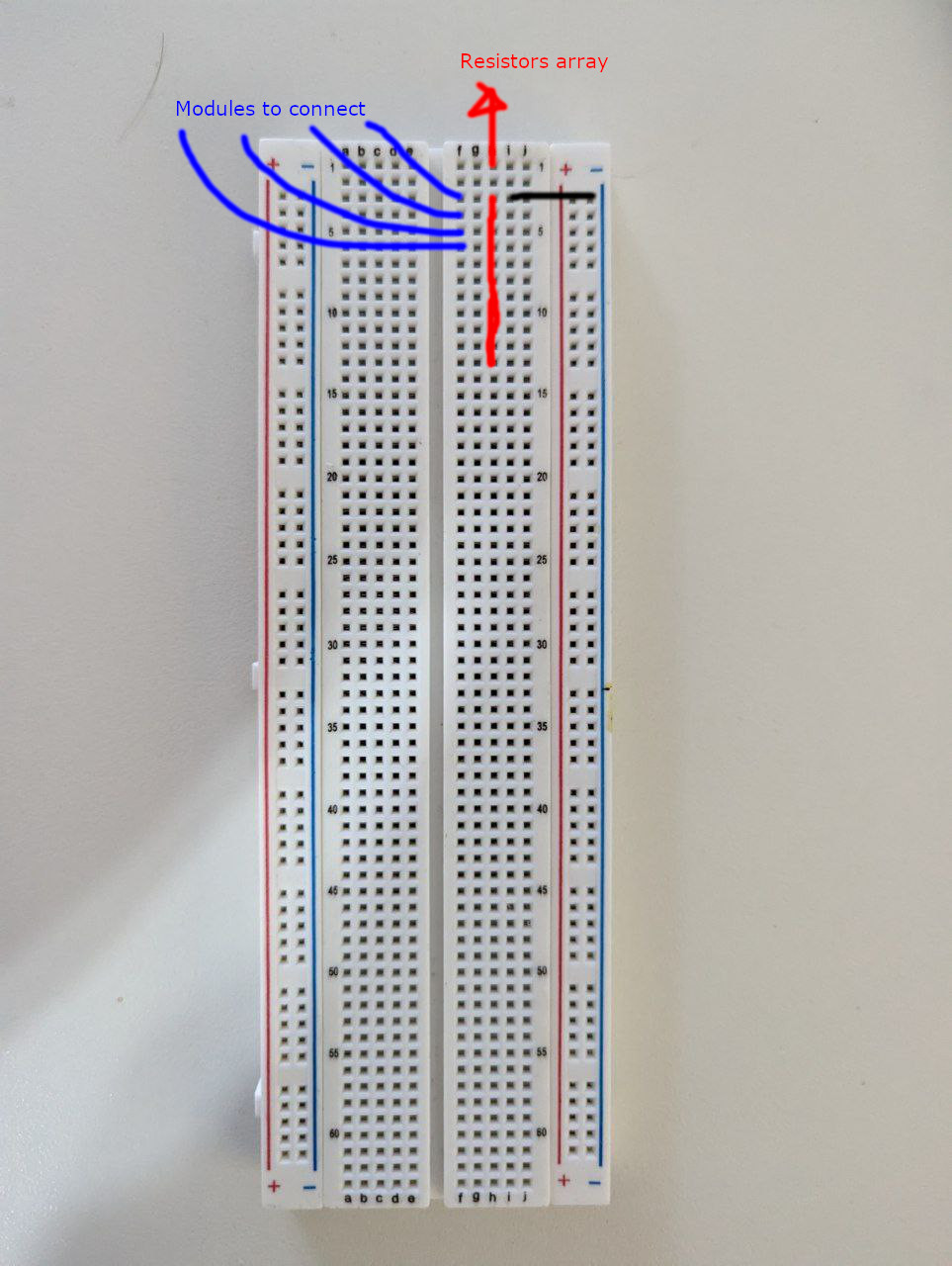
I have a question regarding the simple and efficient connection of the ground cable to a resistor array on a breadboard. Specifically, I'm wondering if there's a component that can help me connect all the ground pins to each pin on the breadboard matrix effortlessly.
Here's the scenario: I'm working on a project that involves multiple resistors connected in an array, and I need to ensure that all the ground connections from each resistor are properly established on the breadboard. While I could individually connect each ground pin to its respective position on the breadboard, it seems quite time-consuming and prone to errors.
So, I'm reaching out to this knowledgeable community to see if there's a solution to simplify this process. Is there a component or technique that I can use to conveniently connect all the ground pins to each pin on the breadboard matrix? Ideally, I'm looking for a method that is efficient, reliable, and doesn't require a lot of manual wiring.
Any insights, recommendations, or tips would be greatly appreciated. Thank you all in advance for your support and expertise!
Components I'm using:
Aren't those resistor arrays already bused? Ie one pin common to all resistors, and 8pins for the other ends? It doesn't seem to make sense to be grounding the unconnected ends...
I thought that the whole point of a resistor array was that it has only a single common connection to the resistors so I do not understand your question
For example, for an 8 resistor array there will be 8 resistor connections and a single common connection
Oh, wow! I'm actually quite new to this electronics stuff, and I don't have much knowledge yet. So, I was wondering, would the following diagram work?
By connecting just one ground pin to the resistor array, will it propagate the connection to the rest?
Thank you so much in advance!
P.S.: To make the connection from ground to the resistor array, is there something more secure than a regular wire? Like a U-shaped connector or something similar? Thanks!
The array will be like this internally

Your new picture shows one pin of the resistor array connected to both GND and a module. That is wrong. One pin will be the common connection and the other 8 will be the other end of each of the resistors. I assume that you do not have a multimeter. Are there any markings on the array indicating which is the common lead ?
As to connecting the common pin to GND consider using a short length of solid wire. Leads cut from components are ideal for this but I suspect that you do not have any components such as resistors with such leads
Bear in mind that a breadboard should only be used for testing and should your project become permanent the breadboard will not be used anyway
Thank you for all the help @UKHeliBob ! I seriously had no clue what I was doing with this component, but you totally saved the day with your explanation. Now I can finally get back to tinkering and testing things out, armed with the knowledge you've given me. Seriously, you're a lifesaver!
Thanks a million!!
Hi @TomGeorge ! Thanks for this info! I will check the component 
Usually the pin marked with a white blob (the left hand one in @TomGeorge diagram) is connected to earth. It will not do any harm to check.
G
Thanks for the info @Zardof !!