read up on shiftOut(), that's a bit-banged version of SPI that can use any pins.
Rob
read up on shiftOut(), that's a bit-banged version of SPI that can use any pins.
Rob
doesn't really help, first off it's using 74HC595's..
all i need is some simple code to see the 3 digits actually working.. can we stay away from SPI, i'm already confused with all this, i have wiring back to 10,11, 12 (max 12,13, 1)
ok, nevermind a sample code.. i have 11 buttons i would like to connect to it
SEQUENCE
button 11 will "set/initiate" the display to - - - .. all other buttons are useless until this happens
buttons 1 through 10 will set the display to show in the display.. each button will have 2 values per say.. example:
button 1 is to be considered A & 1
button 10 is to be considered J & 10
you can see the rest in between.. so say i wanted the display to show b06, i would press button 2 and then press button 6 and then press button 1 - (a certain set of leds will be lit, but we are not at this step yet) and then blanks out the display - i would like to store a value that this button has been pressed at this point
END OF SEQUENCE
thank you
come to think of it - will the 11 buttons need to be connected to another chip?
thank you
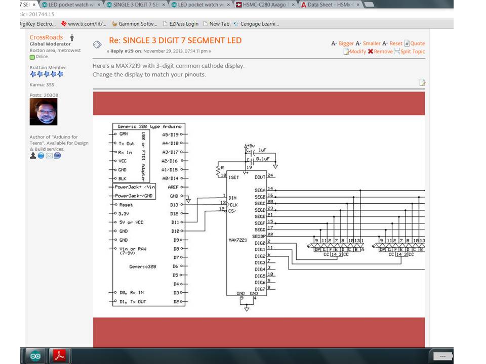
You need to separate your thinking into two parts - the data creation, and the data display.
Plagiarizing BillHo's code some:
#include <SPI.h>

// set up names for the 14 MAX7219 registers:
const byte MAX7219_REG_NOOP        = 0x00;
// codes 1 to 8 are digit positions 1 to 8, see below
const byte MAX7219_REG_DECODEMODE  = 0x09;
const byte MAX7219_REG_INTENSITY   = 0x0A;
const byte MAX7219_REG_SCANLIMIT   = 0x0B;
const byte MAX7219_REG_SHUTDOWN    = 0x0C;
// registers 0x0D and 0x0E are not used
const byte MAX7219_REG_DISPLAYTEST = 0x0F;
// you have 3 digits, so
const byte MAX7219_DIG0        = 0x01;
const byte MAX7219_DIG0        = 0x02;
const byte MAX7219_DIG0        = 0x03;

// 0x00,1,2,3,4,5,6,7,8,9,A,B,C,D,E,F are same as 0,1,2,3,4,5,6,7,8,9,10,11,12,13,14,15

// and 3 variables to hold data - you will change these later to have different things displayed
byte digit0 = 3;
byte digit1 = 6;
byte digit2 = 9;

byte latchPin = 10; // or whatever pin you used
// 13 SCK will connect to MAX7219 clock
// 11 MOSI will connect to MAX7219 serial data in

// now put some data in the MAX7219 registers, and setup the latchPin - backing off from the function calls

void setup ()
  {
Serial.begin(9600); // setup serial communications for debugging
pinMode (latchPin, OUTPUT);
digitalWrite (latchPin, HIGH);

// turn on SPI library - sets  up the internal hardware for SCK, MISO, MOSI
SPI.begin (); // transfers to the MAX7219 will use default speed of 4 MHz

// now setup the 5 registers that control things
digitalWrite (latchPin, LOW);
SPI.transfer (MAX7219_REG_SCANLIMIT);      // send address
SPI.transfer (2); // send data to show 3 digits
digitalWrite (latchPin,  HIGH); // data latched on this signal going Low to High

//continue for the other registers
digitalWrite (latchPin, LOW);
SPI.transfer (MAX7219_REG_DECODEMODE);      // send address
SPI.transfer (0xFF); // use internal mapping to create the digits
digitalWrite (latchPin,  HIGH); // data latched on this signal going Low to High

//continue for the other registers
digitalWrite (latchPin, LOW);
SPI.transfer (MAX7219_REG_DISPLAYTEST);      // send address
SPI.transfer (0); // no display test (display test on turns on all segments)
digitalWrite (latchPin,  HIGH); // data latched on this signal going Low to High

//continue for the other registers
digitalWrite (latchPin, LOW);
SPI.transfer (MAX7219_REG_INTENSITY);      // send address
SPI.transfer (7); // mid level intensity, 0 to 15
digitalWrite (latchPin,  HIGH); // data latched on this signal going Low to High

//continue for the other registers
digitalWrite (latchPin, LOW);
SPI.transfer (MAX7219_REG_SHUTDOWN);      // send address
SPI.transfer (1); // 1 = not shutdown mode
digitalWrite (latchPin,  HIGH); // data latched on this signal going Low to High

// MAX7219 control registers all set, send some data!
Serial.println ("MAX7219 Setup done");

//continue for the data registers
digitalWrite (latchPin, LOW);
SPI.transfer (MAX7219_DIG0);      // send address
SPI.transfer (digit0); // data
digitalWrite (latchPin,  HIGH); // data latched on this signal going Low to High

//continue for the data registers
digitalWrite (latchPin, LOW);
SPI.transfer (MAX7219_DIG1);      // send address
SPI.transfer (digit1); // 1 = not shutdown mode
digitalWrite (latchPin,  HIGH); // data latched on this signal going Low to High

//continue for the other registers
digitalWrite (latchPin, LOW);
SPI.transfer (MAX7219_DIG2);      // send address
SPI.transfer (digit2); // 1 = not shutdown mode
digitalWrite (latchPin,  HIGH); // data latched on this signal going Low to High

Serial.println ("End of Setup");
}   // end of setup
void loop(){
}
That should display 3,6,9 for you and send a couple of message to the serial monitor at 9600.
You should be able to read this and find the matching portions of the datasheet to see where the info is coming from.
Get this working, we can discuss reading buttons, changing the values in digit0,digit1, digit2, and sending the updated digits to the MAX7219 for display updates. That will happen in void loop(), which is currently empty.
const byte MAX7219_DIG0 = 0x02;
error.. says redefinition of 'const byte MAX7219_DIG0'
changed
const byte MAX7219_DIG0        = 0x01;
const byte MAX7219_DIG0        = 0x02;
const byte MAX7219_DIG0        = 0x03;
to
const byte MAX7219_DIG0        = 0x01;
const byte MAX7219_DIG1        = 0x02;
const byte MAX7219_DIG2        = 0x03;
and it uploaded, but nothing happened - all blank
Looks like Bob was caught by the old cut and paste bug.
I think
const byte MAX7219_DIG0 = 0x01;
const byte MAX7219_DIG0 = 0x02;
const byte MAX7219_DIG0 = 0x03;
should be
const byte MAX7219_DIG0 = 0x01;
const byte MAX7219_DIG1 = 0x02;
const byte MAX7219_DIG2 = 0x03;
Rob
i mentioned that already before you posted
thank you
Did you change the wiring between the Arduino and the MAX7219 as well?
i mentioned that already before you posted
Yep, posts crossed, but mine was first by 3 seconds ![]()
PIN Max7219
1 = E 21
2 = D 23
3 = DP 22
4 = C 20
5 = G 17
7 = B 16
8 = common 6
9 = common 11
10 = F 15
11 = A 14
12 = common 2
DIN - 12
clock - 11
load - 10
max - 4 & 9 ground
max - 19 power
that's how i have it wired
do i have any of it right? took me awhile to wire it up and i don't read diagrams like that well..
the one i go by is
Do you have:
Arduino-D13 to MAX7219-13?
Arduino-D11 to MAX7219-1?
Arduino-D10 to MAX7219-12?
If you don't have those control signals connected, the MAX7219 is not going to work with the code provided.
yes and still nothing..
also as far as i can gather this segment is an LDS-3361 AX/BX
datasheet: MAX7219datasheet
and as far as i can see, i have my wiring right.. maybe i'm wrong but i don't believe so
Is yours the AX or the BX?
You said back in reply #12 "3bit Common Anode Digital Tube 0.36in. red LED" which would be BX, which isn't going to work.
Your big picture a few posts back also did not show any capacitors or a resistor from MAX7219 pin 18 to +5, 22K to 33K. Those are also needed.
i have put a resistor max 19 to +5 ![]()
ebay purchase info i got was: 2pcs 3bit Common Anode Digital Tube 0.36in. red LED (121031393167)
the seller: e_goto
i contacted seller and they gave the following:
Here is the data download link:
http://www.icstation.com/ebay/IMAGE_DING/1866.jpg
so as far as AX or BX i do not know or if it's either on 1 side of the display it says 3361BS. and as far as capacitors and resistors i haven't used any simply because i do not know where they go or how many and nobody showed me that.
is it really that complicated to get this single 3 digit segment display to work? if so, i'll just get a couple of different ones cause i'm finding this to be too much BS for these displays! i mean really.. a lot of work just to get numbers and letters to show and i haven't even got to the 11 buttons yet to make it display what i want it to display yet. ![]()
i've tried to be really nice on here as a new member, but i'm just about reaching the point of like wth.. tons of "experts" on here and we can't get this display to work? and yet to see someone confirm the wiring i have is correct or incorrect.
thank you
cupstacker:
i've tried to be really nice on here as a new member, but i'm just about reaching the point of like wth.. tons of "experts" on here and we can't get this display to work? and yet to see someone confirm the wiring i have is correct or incorrect.
Despite your frustration, don't take it out on the people here who are trying to help you for free.
Your wiring descriptions have been inconsistent, which makes it hard to work out the issue.
A few posts back you said this:
DIN - 12
clock - 11
load - 10
which is inconsistent with:
Arduino-D13 to MAX7219-13?
Arduino-D11 to MAX7219-1?
Arduino-D10 to MAX7219-12?
The photo you took earlier only showed the breadboard, and not how it was connected to your Arduino.
cupstacker:
and yet to see someone confirm the wiring i have is correct or incorrect.
Give us a complete photo of your setup and we may be able to do this.
cupstacker:
as far as capacitors and resistors i haven't used any simply because i do not know where they go or how many and nobody showed me that.
I linked this page before. Did you visit it?
Here's a diagram from that page:
is it really that complicated to get this single 3 digit segment display to work?
It shouldn't be. Since you have worked out the pin-outs can you use a meter, or a 5v power supply and a resistor (like 220 ?) in series, and work out which way around the LEDs are. You know the common pins (8, 9, 12). Are they anodes or cathodes?
tons of "experts" on here and we can't get this display to work?
"We?". If you expect help you need to do better than a graphic with a few boxes and coloured lines. We aren't mind readers, experts or not. Draw exactly how you have wired it up, using pencil and paper if you have to, and scan it it. And/or take a photo. And post the exact code you are using. A one-line bug in the code, or a single wire in the wrong place can do it.
image 1: http://cdn.img42.com/2513ad9a3bed0caca272d8150ff9f7a2.jpeg
image 2: http://cdn.img42.com/f6acb94b233f0db61910b3859e1218d7.jpeg
just shows 888 or (blank if i unplug and replug it a few times)
@ nick - anodes.. already been mentioned, and as far as "taking it out" on anyone, i'm not - just venting.. 2 days here and i still all i see is 888 being displayed. so yes, i am a little frustrated.
ps
and yes, we know we are getting help for free, we all know this - i wish people would stop rubbing that into new people's faces already. we appreciate the help, but that doesn't mean we can't vent at times.
What have you got on pin 18 of the MAX7219? That controls current output, and you aren't indicating anything in your earlier reply. Without current control you can burn out your LEDs.

