2-digit 7-segment display (10 pin) with MAX7219

Howdy,
Regarding Arduino to MAX7219 to a 2-digit 7-segment display: Can you help me display segments on demand?
I know this is an old topic for many. I've looked through posts, tested code, and I'm not sure what the problem is.
Is there something wrong with my setup?

Long term goal: Read time digits from an RTC (hh:mm:ss).
Short Term goal: just cycle thru 00-99.

I'd like to produce code similar to shiftOut(); but tailored to the MAX7219, probably with SPI? I'm new to MAX and SPI. I'm open to whatever works:

  digitalWrite(latchPin, LOW);
  shiftOut(dataPin, clockPin, MSBFIRST, number_value[ss]); // sec
  shiftOut(dataPin, clockPin, MSBFIRST, number_value[mm]); // min
  shiftOut(dataPin, clockPin, MSBFIRST, number_value[hh]); // hour
  digitalWrite(latchPin, HIGH);

All tests so far have produced just erratic blips, but each segment blips once in a while so I believe they're all connected. At this point I just want to see some digits.

I've got the following setup:

[ Arduino pins ] [ MAX7219 pins ] [ 2-dig/7-seg pins ]
10 12 LOAD
11 13 CLK
12 1 DIN
+5v +10k resistor 18
+5v (no resistor) 19
GND 4
GND 9
2 Digit 1 10
11 Digit 2 5
14 Seg A 3
15 Seg F 4
16 Seg B 9
17 Seg G 1
20 Seg C 8
21 Seg E 7
22 Seg DP 2
23 Seg D 6

MAX7219 datasheet: https://datasheets.maximintegrated.com/en/ds/MAX7219-MAX7221.pdf
CL3621AH 2-digit 7-Segment display datasheet: http://www.xlitx.com/datasheet/CL3621AH.pdf

CL3621AH-pins.png

CL3621AH-pins.png

what happens if you try the library "led control" from the Arduino IDE?

Max7219 is not simply a bunch of shift registers inside a single chip. It is more sophisticated than that, with different registers controlling brightness, number of digits and other options, as well as the data that is to appear on each digit. It can all be done with shiftOut(), but you need to know exactly what data to send in what sequence. For a beginner, it's a good idea to use a library that will take care of all those details for you. There are a number of different libraries for use with max7219, but the one suggested by noiasca is probably the simplest for a beginner.

Right. Thank you noiasca & PaulRB.

noiasca:
what happens if you try the library "led control" from the Arduino IDE?

Okay. noiasca, you said, "from the Arduino IDE" and in case I'm missing something I want to clarify: I'm using the LedControl Library by Eberhard Fahle v.1.0.6. Please let me know if you're referring to a different "led control" library.

Now, remember, I'm using one 2-digit 7-segment display. When I try the LedControl library example code "LCDemo7Segment" I get one blip at upload, then dark. However, that code is intended for "at least four 7-Segment digits." For reference, here's that example code:

//We always have to include the library
#include "LedControl.h"

/*
 Now we need a LedControl to work with.
 ***** These pin numbers will probably not work with your hardware *****
 pin 12 is connected to the DataIn 
 pin 11 is connected to the CLK 
 pin 10 is connected to LOAD 
 We have only a single MAX72XX.
 */
LedControl lc=LedControl(12,11,10,1);

/* we always wait a bit between updates of the display */
unsigned long delaytime=250;

void setup() {
  /*
   The MAX72XX is in power-saving mode on startup,
   we have to do a wakeup call
   */
  lc.shutdown(0,false);
  /* Set the brightness to a medium values */
  lc.setIntensity(0,8);
  /* and clear the display */
  lc.clearDisplay(0);
}


/*
 This method will display the characters for the
 word "Arduino" one after the other on digit 0. 
 */
void writeArduinoOn7Segment() {
  lc.setChar(0,0,'a',false);
  delay(delaytime);
  lc.setRow(0,0,0x05);
  delay(delaytime);
  lc.setChar(0,0,'d',false);
  delay(delaytime);
  lc.setRow(0,0,0x1c);
  delay(delaytime);
  lc.setRow(0,0,B00010000);
  delay(delaytime);
  lc.setRow(0,0,0x15);
  delay(delaytime);
  lc.setRow(0,0,0x1D);
  delay(delaytime);
  lc.clearDisplay(0);
  delay(delaytime);
} 

/*
  This method will scroll all the hexa-decimal
 numbers and letters on the display. You will need at least
 four 7-Segment digits. otherwise it won't really look that good.
 */
void scrollDigits() {
  for(int i=0;i<13;i++) {
    lc.setDigit(0,3,i,false);
    lc.setDigit(0,2,i+1,false);
    lc.setDigit(0,1,i+2,false);
    lc.setDigit(0,0,i+3,false);
    delay(delaytime);
  }
  lc.clearDisplay(0);
  delay(delaytime);
}

void loop() { 
  writeArduinoOn7Segment();
  scrollDigits();
}

So I modified it, basically reduced it to the scrollDigits() function. Now it should simply write to the two digits. And it does, kind of. I get strange results. Reliably displays some numbers, reliably blips left-digit on most other combinations, and unreliably displays some combinations.

/*
 * currently this will display "41" on the 7-segment display.
 * this works for: 11, 41, 51, 71, 44, 54, 74,
 * this blips once (left digit only) then dark for all other number combinations.
 * I did NOT try every number combination
 */
#include "LedControl.h"
LedControl lc = LedControl(12, 11, 10, 1);

unsigned long delaytime=250;

void setup() {
  lc.shutdown(0, false);
  lc.setIntensity(0, 10);
  lc.clearDisplay(0);
}

void digits(){
  lc.setDigit(0, 1, 4, false); // left digit
  lc.setDigit(0, 0, 1, false); // right digit
  delay(delaytime);
}

void loop() {
  digits();
}

And that's the best I've got so far.
I did test a version where I use a for-loop on the digits() function like the original example, but this yields one blip then nothing.

/*
 * Note: the digits() function for loop. 
 * This gets one blip then dark.
*/
#include "LedControl.h"
LedControl lc = LedControl(12, 11, 10, 1);

unsigned long delaytime = 250;

void setup() {
  lc.shutdown(0, false);
  lc.setIntensity(0, 10);
  lc.clearDisplay(0);
}

void digits() {
  for (int i = 0; i < 9; i++) {
    lc.setDigit(0, 1, i, false); // left digit
    lc.setDigit(0, 0, i+1, false); // right digit
    delay(delaytime);
  }
  lc.clearDisplay(0);
  delay(delaytime);
}

void loop() {
  digits();
}

So that's it. The middle code above is the closest I've come. I've swapped 4 other 7-seg displays with same results each time. Sure could use some help thinking this through.
Cheers-

2 Digit 1 10
11 Digit 2 5

Things might make more sense if you use the pins for digits 0 & 1 rather than digits 1 & 2?

PaulRB:
Things might make more sense if you use the pins for digits 0 & 1 rather than digits 1 & 2?

I used "1" and "2" simply because the datasheet calls em that. But yes the table would be better written as you suggest:
MAX pin 2 to 7-Seg pin 10
MAX pin 11 to 7-Seg pin 5

The fact that your display has only 2 digits, not 4, should not stop the demo sketch from working.

Have you tried replacing the max chip?

Have you checked the part number printed on the side of the display matches the data sheet you posted? For example could you be using a common anode display instead of common cathode?

Have you tested the display in isolation by probing the anode & cathode pins one at a time with connecting wires and a series resistor (eg. 330R)?

Can you post some clear, bright photos of the circuit that show how you have connected everything?

in other words:

We know that this library is working.
If it doesn't work for you - you either have a wrong wiring or damaged parts.

You can use these methods

 void setLed(int addr, int row, int col, boolean state);

and

 void setRow(int addr, int row, byte value);
void setDigit(int addr, int digit, byte value, boolean dp);

it should be straight forward to analyse what's going wrong with your setup.

  • check, if have you connected to the proper colums
  • check, if have you connected to the right segments

if you can't make it working,
show your testsketch
show a picture what you get
give a description what you want

PaulRB:
The fact that your display has only 2 digits, not 4, should not stop the demo sketch from working.

Have you tried replacing the max chip?

Have you checked the part number printed on the side of the display matches the data sheet you posted? For example could you be using a common anode display instead of common cathode?

Have you tested the display in isolation by probing the anode & cathode pins one at a time with connecting wires and a series resistor (eg. 330R)?

Can you post some clear, bright photos of the circuit that show how you have connected everything?

Thank you. Yes. I've replaced the Arduino, the MAX chip, the 10uF and the 0.1uF capacitors, the 10k resistor, the display, and I've rewired it. Several times. The display is common cathode. I've not tested in isolation, but I have verified that each segment will illuminate on command; they just don't seem to work when I illuminate enough of them to form the number, "76", for example. In that case, the display fails. I can't post a photo of the circuit that will be any more helpful than the fritzing images above. I could attempt a circuit diagram if you feel that might help, but I humbly suggest I've set this up according to your specifications, as shown in the fritzing images above.

Could I be wrong in using a 10k resistor, 10uF and 0.1uF capacitors? That's something I'm not really knowledgeable about.

noiasca:
in other words:

We know that this library is working.
If it doesn't work for you - you either have a wrong wiring or damaged parts.

I cannot deny the logic of your words.
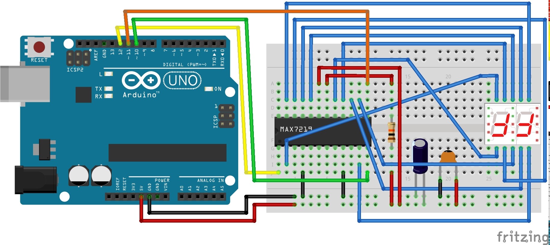
So if we go with that, could a display be damaged such that (A) it works fine with I wire directly from Arduino to display with no MAX chip (which I discuss here: Controlling 10-pin 2-digit 7-segment Display with shift register. - #8 by cdrk - LEDs and Multiplexing - Arduino Forum) and then (B) it fails confusingly when paired with a MAX chip?

The following code is my test of the LedControl library functions. It's a bit long and remedial, but I prove that each segment will light up on command. They just won't always light up in every grouping I ask for. Some groupings work. Some don't.

/*
   an attempt to better understand the LedControl Library
   for use with a 2-digit 7-segment display
   https://www.arduino.cc/reference/en/libraries/ledcontrol/
   http://wayoda.github.io/LedControl/pages/software

   setRow(int addr, int row, byte value);
   setColumn(int addr, int column, byte value);
   setLed(int addr, int row, int col, boolean state);
   setDigit(int addr, int digit, byte value, boolean dp);

*/
#include "binary.h"
#include "LedControl.h"
LedControl lc = LedControl(12, 11, 10, 1);

unsigned long delaytime = 500;

void setup() {
  lc.shutdown(0, false);
  lc.setIntensity(0, 4);
  lc.clearDisplay(0);
}

// ------------- setRow(int addr, int row, byte value);
void test_setRow() {
  lc.setRow(0, 0, B00011101);
  lc.setRow(0, 1, B01100011);
  delay(delaytime);
  lc.setRow(0, 0, B01100011);
  lc.setRow(0, 1, B00011101);
  delay(delaytime);
  lc.clearDisplay(0);
}
// cycle through each segment; verifies each segment works
void cycleThru_setRow() {
  lc.setRow(0, 0, B10000000); // dp
  lc.setRow(0, 1, B10000000);
  delay(delaytime);
  lc.setRow(0, 0, B00000000); // blank
  lc.setRow(0, 1, B00000000);
  delay(delaytime);
  lc.setRow(0, 0, B10000000); // dp
  lc.setRow(0, 1, B10000000);
  delay(delaytime);
  lc.setRow(0, 0, B01000000); // A
  lc.setRow(0, 1, B01000000);
  delay(delaytime);
  lc.setRow(0, 0, B00100000); // B
  lc.setRow(0, 1, B00100000);
  delay(delaytime);
  lc.setRow(0, 0, B00010000); // C
  lc.setRow(0, 1, B00010000);
  delay(delaytime);
  lc.setRow(0, 0, B00001000); // D
  lc.setRow(0, 1, B00001000);
  delay(delaytime);
  lc.setRow(0, 0, B00000100); // E
  lc.setRow(0, 1, B00000100);
  delay(delaytime);
  lc.setRow(0, 0, B00000010); // F
  lc.setRow(0, 1, B00000010);
  delay(delaytime);
  lc.setRow(0, 0, B00000001); // G
  lc.setRow(0, 1, B00000001);
  delay(delaytime);
  lc.clearDisplay(0);
}

// ------------- setColumn(int addr, int column, byte value);
void test_setColumn() {
  lc.setColumn(0, 1, B01000000); // left (tens)
  lc.setColumn(0, 6, B01000000);
  // lc.setColumn(0, 5, B01000000); // add this line and it fails
  lc.setColumn(0, 0, B11000000); // both left and right digits
  lc.setColumn(0, 7, B11000000);
  lc.setColumn(0, 4, B10000000); // right (ones)
  lc.setColumn(0, 3, B10000000);
  delay(delaytime);
  lc.clearDisplay(0);
}

// ------------- setLed(int addr, int row, int col, boolean state);
void test_setLed() { // setLed(addr, row, col, boolean state);
  for (int i = 0; i < 9; i++) {
    lc.setLed(0, 0, i, true);
    lc.setLed(0, 1, i, true);
    delay(delaytime);
    lc.setLed(0, 0, i, false);
    lc.setLed(0, 1, i, false);
  }
  delay(delaytime);
  lc.clearDisplay(0);
}

// ------------- setDigit(int addr, int digit, byte value, boolean dp);
void test_setDigit() { // display "41"
  lc.setDigit(0, 1, 4, false); // left digit
  lc.setDigit(0, 0, 1, false); // right digit
  delay(delaytime);
  lc.clearDisplay(0);
}
void test_printNumber(int n) {
  int ones;
  int tens;
  ones = n % 10;
  n = n / 10;
  tens = n % 10;
  n = n / 10;
  lc.setDigit(0, 1, (byte)tens, false);
  lc.setDigit(0, 0, (byte)ones, false);
  delay(delaytime);
  lc.clearDisplay(0);
}

void loop() {
  test_setLed();
  test_setColumn();
  //  cycleThru_setRow();
  test_setRow();
  // if test_setDigit() or test_printNumber() are first in loop()
  // then loop() fails, but loop() works  if these two are down here.
  test_setDigit();
  test_printNumber(72); // change this to "76" and digits go dark evermore.
}

I really don't know what to conclude. But I thank you BOTH for your help.

Actually, at the bottom of the code above, in the loop(); function I point out that the arrangement of the functions called influences the success of the display. Could that be a clue?

void loop() {
  test_setLed();
  test_setColumn();
  //  cycleThru_setRow();
  test_setRow();
  // if test_setDigit() or test_printNumber() are first in loop()
  // then loop() fails, but loop() works  if these two are down here.
  test_setDigit();
  test_printNumber(72); // change this to "76" and digits go dark evermore.
}

It is very strange. It seems like you found a bug in the library, but that's been around for at least 6 years, you would think most bugs would have been found & fixed by now.

Unfortunately, checking my parts bins, I don't have a max chip around to try to reproduce your problem. Maybe I'll order a couple.

PaulRB:
It is very strange. It seems like you found a bug in the library, but that's been around for at least 6 years, you would think most bugs would have been found & fixed by now.

In the toneless void of screen-text I cannot be sure, but I think you must be joking. Surely the problem is on my side.

I've tried 3 different Arduino UNO boards, 3 different 10k resistors (Brown Black Orange Gold), 3 diff 10uF caps, 3 diff 0.1uF caps. I have 10 MAX7219 chips and tried 'em all.

Question: Have I put the capacitors in the right location (see above)?
Obvs: Anode (long leg) to (+) and Cathode (short leg) to (-).

Arduino pins 10, 11, 12, connect to MAX pins 12, 13, 1, respectively.
Arduino GND to MAX 4 and 9.
Arduino 5v to a 10k resistor and on to MAX pin 18.
Arduino 5v to MAX pin19 directly (no resistor.)

I'm going to rebuild from scratch again and see what I can learn.

[smacks head]

OMG. SOLVED. [[ edited a few days later: Solution doesn't universally clarify all cases of earlier failure.]]

The Breadboard. I'd pressed the CL3621AH display securely into the breadboard, as one does. And I had display problems. While muttering a curse of disgruntlement, I gently pulled the display up a little and noticed a previously dark segment illuminate. By simply lifting the segment up, just a little, out of the fullest depths of the breadboard I was able to achieve a proper connection.

I could not have persisted without your help. So Thank you for bouncing ideas at me!!!

The following code cycles 00-99 on a 2-digit 7-segment display (CL3621AH) with a MAX7219 chip.

/*
 * This code counts up from 00-99 
 * on a 2-digit 7-segment display
 * 
*/
#include "binary.h"
#include "LedControl.h"
LedControl lc = LedControl(12, 11, 10, 1);

unsigned long delaytime = 500;

void setup() {
  lc.shutdown(0, false);
  lc.setIntensity(0, 4);
  lc.clearDisplay(0);
}

void test_printNumber(int n) {
  int ones;
  int tens;
  ones = n % 10;
  n = n / 10;
  tens = n % 10;
  n = n / 10;
  // setDigit(int addr, int digit, byte value, boolean dp);
  lc.setDigit(0, 0, (byte)tens, false);
  lc.setDigit(0, 1, (byte)ones, false);
  delay(delaytime);
  lc.clearDisplay(0);
}
void countUp(){
  for (int i=0; i<100; i++){
    test_printNumber(i);
  }
}
void loop() {
    countUp();
}

SOLVED [[ edited a few days later: Solution doesn't universally clarify all cases of earlier failure.]]

I think you must be joking

No, I was being completely genuine. What you described in reply #9 indicated that the display worked perfectly if code contained certain pattern sequences in a certain order, and did not work if some of those sequences were not present or were in a different order. To my mind this indicated a software bug somewhere, but I could see no problems in the code you posted, so wondered about the library. But as noiasca said, this library is well known and well trusted for many years, so finding a bug there would be very unlikely.

Certainly what you described in reply #9 cannot be explained by unreliable breadboard connections. Changing the code cannot lift the display slightly from the breadboard, causing it to start working.

PaulRB:
Certainly what you described in reply #9 cannot be explained by unreliable breadboard connections. Changing the code cannot lift the display slightly from the breadboard, causing it to start working.

Yes, I see your point.

In other words, because I was able to illuminate each digit while testing earlier code, that suggests there was no "breadboard interference". And if that's true, then adjusting how the display is seated in the breadboard should not result in solution.

I am without answers.

Along similar lines, I've wondered why (if/how) physically moving the display could affect its performance. Could a 7-segment display be damaged in such a way that it would (a) meet the earlier success of lighting each segment individually, (b) fail to light certain sets of segments ("76" for example) and then (c) perform flawlessly when the display is adjusted physically? Could a loose pin work for one segment but fail when multiple segments are lit, and then work when slight torque or pressure is applied? Maybe it's not simply the lifting up out of the breadboard but rather a change in the display?
Nothing appears loose. There is no film or coating on the pins that I can detect.

Gremlins, perhaps?

I am eager to solder these to proto-boards for the intended project (clock) and I'm not entirely confident yet that they will perform. But that's my next milestone for these displays.

7-seg displays are pretty simple inside. Just a bunch of LEDs with common anode and common cathode connections. Can't imagine how unreliable connections could cause the symptoms you described.

Here's another idea: switch to a different library (will require some code changes) and see if the problem persists.

The developer of that library is a forum member here and very helpful.

PaulRB:
7-seg displays are pretty simple inside. Just a bunch of LEDs with common anode and common cathode connections. Can't imagine how unreliable connections could cause the symptoms you described.

Here's another idea: switch to a different library (will require some code changes) and see if the problem persists.

GitHub - MajicDesigns/MD_MAX72XX: LED Matrix Library

The developer of that library is a forum member here and very helpful.

I'll have a look at that library.
Meanwhile I edited my previous "solved" declaration to read:
SOLVED [[ edited a few days later: Solution doesn't universally clarify all cases of earlier failure.]]
I am still experiencing cases where the display fails when pressed in deep to the breadboard, but if removed, and the sketch reloaded, and display reinserted shallowly, it works. I feel like this gives me a 50% chance of success when I solder it, which is iffy.

This topic was automatically closed 120 days after the last reply. New replies are no longer allowed.