Sizing transformer for linear DC supply

Hi Folks.

Yeah, I'm still around. Just have a lot of distractions these days. Anyways ...

The 6V 2A switching supply for my Pila IBC charger went bonkers on me. I use this thing every day. I have some backup in place, but need to get it replaced. So, of course, I'm thinking of building one, instead of buying. Yeah, likely not cost-effective. But I'll feel better about the reliability of a plain linear supply, vs. a random wall wart switcher I find on the web.

Not sure the LM350 regulator is the best choice, but I'm sure it'll work, and it has plenty of headroom. (I note that the Pila charger itself calls for 6VDC 2-3A, so I'm not sure why they supplied a 2A supply.) I can choose caps from the datasheet, I think, and toss in a fuse and some protection diodes, but below is the basic circuit.

Question is, how do I size the transformer. I've killed about an hour looking for a decent tutorial on the web, and come up empty. I'm thinking 15W 12V secondary, but I could be way off. I'm figuring ~2V drop on the regulator, and 1.7 for the bridge, giving 9.7V, and then just adding some headroom. But some of what I've read indicates I need to account for ripple voltage, which, now I think on it, probably influences the specs for the filter cap coming after the bridge too.

Pointers to good tutorials, references, etc. appreciated.
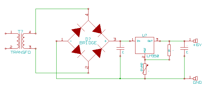
6vsupply.gif

http://homemadecircuitsandschematics.blogspot.sg/2012/03/how-to-design-power-supply-simplest-to.html
http://www.zen22142.zen.co.uk/Design/dcpsu.htm

BillHo:
http://www.zen22142.zen.co.uk/Design/dcpsu.htm

Thanks for the suggestions, but I have a hard time trusting a site providing an equation which produces clearly nonsensical results. The author give mV = mA/2fC for calculating the ripple voltage, and states capacitance is in Farads. So, I can use V and A to suit my application, since mA is on the top of the fraction, so I'm just multiplying both sides by 1000. And, just for fun, lets use a 1 mF filter capacitor.

2/2*60*.000001 = 16,666.66......

I'll grant that 1mF would be a dump cap to use, but I don't believe there's any way to get a kilovolt ripple from a 12VAC transformer output. He provides a shortcut for 50hz, wherein capacitance is in microfarads, and using that as the unit gives more believable results, but even so, one could still then use a very high value capacitor, and still get clearly bogus numbers.

So, anyway, I'm still looking for how to spec out the proper transformer.

The biggest concern I have is with the power dissipation in the regulator. I'm pretty sure you can overheat the thing (depending on the heatsink) at less than 3 Amps when there's more than a couple of volts dropped across the regulator.

It's been a long time since I've calcuated ripple. The voltage regulator will knock-out the ripple, as long as the ripple doesn't exceed the point where the voltage regulator drops-out. So, I usually just use a capacitor that's 1000uF or more, one that's available, and one that will fit physically. (A higher voltage into the regulator will tend to minimize ripple problems, but more it's more power/heat in the regulator.)

I'm thinking 15W 12V secondary, but I could be way off. I'm figuring ~2V drop on the regulator, and 1.7 for the bridge, giving 9.7V, and then just adding some headroom.

12VAC is plenty for a 6VDC supply. I think you're forgetting that the peak AC voltage is about 1.4 times the RMS. At 12VAC your capacitor will charge-up to about 17V minus the diode drops. (I'll usually use a 12V transformer for a 12V power supply.) And at no-load, the transformer will probably put-out more than 12VAC. If you can find a 9V transformer, that should be enough.

DVDdoug:
The biggest concern I have is with the power dissipation in the regulator. I'm pretty sure you can overheat the thing (depending on the heatsink) at less than 3 Amps when there's more than a couple of volts dropped across the regulator.

Which is why I want to not oversize the transformer, in terms of output voltage. I will have heatsinking, but no point in pushing that limit, or wasting power.

It's been a long time since I've calcuated ripple. The voltage regulator will knock-out the ripple, as long as the ripple doesn't exceed the point where the voltage regulator drops-out. So, I usually just use a capacitor that's 1000uF or more, one that's available, and one that will fit physically. (A higher voltage into the regulator will tend to minimize ripple problems, but more it's more power/heat in the regulator.)

I'll keep digging on the ripple question.

I'm thinking 15W 12V secondary, but I could be way off. I'm figuring ~2V drop on the regulator, and 1.7 for the bridge, giving 9.7V, and then just adding some headroom.

12VAC is plenty for a 6VDC supply. I think you're forgetting that the peak AC voltage is about 1.4 times the RMS. At 12VAC your capacitor will charge-up to about 17V minus the diode drops. (I'll usually use a 12V transformer for a 12V power supply.) And at no-load, the transformer will probably put-out more than 12VAC. If you can find a 9V transformer, that should be enough.

No, I'm not forgetting about it. I honestly don't know how to treat it. Hence, asking for info. :slight_smile: I understand the notion that as each peak occurs in the rectified voltage, the cap charges up a bit more. And so ... eventually, it would reach peak V. Except that there's a constant discharge as well. We can, as thought expermiment, imagine a load across the capacitor producing an RC time constant less than 1/60th of a second. And maybe, in a practical circuit such as I'm contemplating, this can be simply discounted.

Peak on 6VAC is ~8.5 -- not enough. Peak on 9VAC is ~12.73, so I'd be dropping 5V across the regulator, if the VDC does indeed approach the peak. Going back to my initial back-of-the-napkin 9.7V * 1.414 = 6.86, that get me to this brutishly expensive transformer (for my purposes, anyway). I'm selecting for current output, not VA rating. Moving to 10V out, the price improves considerably, but then I'd be dropping 6V across the regulator.

If it really comes to a $46 transformer to do this well, I might as well buy a new Pila charger -- they're ~$45. Yeah, I've looked at Digikey for a 6V wall-wart supply, which can be had for about $17. Just thought it might be a nice little project to do one evening.

A few points:

  1. VA rating of a transformer is not the same as Watts output. Because of the pulsed nature of the current flowing through the bridge rectifier, you need a transformer with a significantly higher VA rating than is implied by the current you will be drawing. If you want to supply 2A and you use a 10V transformer, I suggest at least a 30VA transformer.

  2. If the voltage drop across the regulator at full load is larger than you want, you can use a smaller capacitor to give a larger ripple voltage and hence a lower average voltage across the regulator. A smaller capacitor also helps with reducing the RMS current drawn from the transformer, and hence keeping within the VA rating.

Example:

10V transformer, 14.14V peak, less nearly 2V in the bridge rectifier gives 12V. Rather high for your 6V regulator, so design for 4V ripple @ 2A load, hence minimum voltage drop across the regulator will be 2V (which should be enough) and average will be around 5V @ 2A load. hence 10W power dissipation, which isn't too difficult to get rid of unless the power supply has to fit in a confined space. Capacitor to get 4V ripple will be somewhat less than (2 * 1/120)/4 F = 4200uF. I suspect 3300uF will be just about enough.

Alternatively, use an 8V transformer such as http://www.digikey.com/product-detail/en/VPP16-1900/237-1076-ND/242520 and design for not more than 1V ripple.

Okay, I'm getting a better mental handle on it now -- thanks. I'll have to read a bit more on the ripple, but I do see the point. Interesting to note that TI recommends an input bypass of 0.1uF ceramic. Due to the discrepancy of capacitance from the values you're recommending, should I assume that the 'bypass' is serving a completely different function here? (I'm aware of bypass as used for, e.g. VCC in to an IC.)

Much better transformer there for my purposes too. My search-fu at Digikey is limited by my lack of knowing better what I'm looking for. This is looking more do-able now.

I assume there aren't any particular gotchas for the bridge IC, as long as I pick one that'll handle the current. This one or any similar.

ETA: Finding more web sites repeating the same ripple calculation. Well, okay, I'll take it on faith. 24 mF gives me .7V ripple, if I'm not dropping a decimal point or something. And that just seems way off. .7 = 2/(120*.024)

justjed:
Interesting to note that TI recommends an input bypass of 0.1uF ceramic. Due to the discrepancy of capacitance from the values you're recommending, should I assume that the 'bypass' is serving a completely different function here? (I'm aware of bypass as used for, e.g. VCC in to an IC.)

Yes, that capacitor is for preventing the regulator from oscillating. Keep it close to the regulator.

justjed:
I assume there aren't any particular gotchas for the bridge IC, as long as I pick one that'll handle the current. This one or any similar.

That one should be just fine.

justjed:
ETA: Finding more web sites repeating the same ripple calculation. Well, okay, I'll take it on faith. 24 mF gives me .7V ripple, if I'm not dropping a decimal point or something. And that just seems way off. .7 = 2/(120*.024)

That's 24 milliFarads for 0.7V ripple, in other words 24000 microFarads. Actual ripple will be a bit less than that, the formula is only approximate.

Those are some pricey caps.

$35 -- cheapest in-stock at Mouser. Same part at Digikey $33

Well, I'll keep plugging at it, but I'm going to work on higher voltage and more ripple.

Again, thanks for the info.

Here is a suitable capacitor that costs much less, around $3: http://uk.farnell.com/epcos/b41231c4229m/capacitor-snap-in-16v-22000uf/dp/1839274.

Well, I finally built this thing. With a 2A load, peak V across a 22000uF smoothing cap is 8.35, with 20mV ripple. (This measured on the landlord's Tektronix o-scope) Output voltage is very stable.

However, the regulator gets quite hot. Landlord is of the opinion the regulator will fry itself. According to the datasheet, it has "full thermal protection", but I haven't let it run to see whether it shuts itself off. Don't have a thermal probe, so I don't know how hot it is, so I don't really know whether it's too hot.

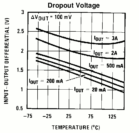
Just pondering where to go from here. I can try a smaller smoothing cap, but if I'm reading the datasheet correctly, I don't have much room to spare with the dropout voltage. I'm considering:

  • Different model regulator
  • Larger heatsink
  • Switch to a LM350 in a TO-3 case

I'm leaning toward the LM350 in a TO-3 case. I have a working circuit. I can clip off the existing regulator, cut a hole in the case, mount the TO-3 externally on a big square of aluminum, and wire to it from the clipped off leads. This appears to be the path of least resistance.

I'm thinking a different regulator will still require a larger heatsink anyway. There is some room inside my case for a larger one, but it'll be a bit tricky.

(Yes, I clipped off the smoothing cap, to try a smaller one, but it was only 1000uF, and the output voltage sagged to 5.5 under load. Well, now I can experiment with other size caps.)

How about a 7.5V supply and then your 6V regulator after that?
http://www.mpja.com/75-Volt-Power-Supply-20A-150W-Switching-Hengfu/productinfo/16018%20PS/

I will add that upon looking again at the datasheet, I'm certainly not using the dropout voltage drawing correctly. So, I think my best course is to try smaller caps until the output sags. And the LM350 in a TO-3 is a spendy item. STMicroelectronics has an LM350 for a lot less. I just wonder how close it is to the TI in characteristics.

CrossRoads:
How about a 7.5V supply and then your 6V regulator after that?
http://www.mpja.com/75-Volt-Power-Supply-20A-150W-Switching-Hengfu/productinfo/16018%20PS/

Well, it's another $28. Cheaper than the TI-LM350 in a TO-3. But I'd like to hang on to the idea of making what I have work, since I seem pretty close. :fearful:

No worries, I came across the topic a little late.

I would use an LM338K Steel it's a 5A 3 terminal regulator, the math to do the heatsink is trivial and on wiki.. and you won't buy anything by 'tuning' the regulator with the input filter value.. When it dries out prematurely due to high ripple currents it won't have far to go to fail, leave it where it is and either put your money in an efficient power supply or into getting rid or your waste energy as heat in an efficient heat waster.. Sinkr.
Seriously an older National Semiconductor LM2596 switcher can be had in the same TO-220 case your 1.5 A (Read the Specs carefully the LM350T is a 1.5A part it's the K version that is rated @ 3A) linear regulator and it would require a minimal heatsinking.. I used a 6 mm extension of the PCB copper around the part in a 2 A 6V PSU once with a half a dozen via's to the same area on the backside of the board.. It worked well. An older part like this one is easy to use through hole and entirely buildable even by the relatively inexperienced, The PCB app notes are perfectly applicable to NON PCB environments as they refer mainly to grounding and the relative lead-length's length of 3 critical parts, the switch, the catch diode and the inductor and in the end all they say is that they 'should' be as short as possible, Oh yeah and a star ground works the best...
The best part is that you've probably bought too much transformer.. So it will at least last a long time..

Doc

What size heatsink do you have on the regulator? With a 2A load it will only dissipate 5W, and the TO220 version should be able to handle that easily, with a modest heatsink. The worst case thermal resistance die-to-case is listed on the OnSemi datasheet as 2.3C/W and the maximum operating temperature is 125C. So you only need to keep the case temperature below about 100C for the regulator to function properly.

Docedison:
... you won't buy anything by 'tuning' the regulator with the input filter value.. When it dries out prematurely due to high ripple currents it won't have far to go to fail, leave it where it is and either put your money in an efficient power supply or into getting rid or your waste energy as heat in an efficient heat waster.. Sinkr.

... your 1.5 A (Read the Specs carefully the LM350T is a 1.5A part it's the K version that is rated @ 3A) linear regulator and it would require a minimal heatsinking

The TI datasheet I have makes no distinction between the T and the K. Here's what seems relevant.

These specifications are applicable for power dissipations up to 30W for the TO-3 (NDS) package and 25W for the TO-220 (NDE) package. Power dissipation is ensured at these values up to 15V input-output differential. Above 15V differential, power dissipation will be limited by internal protection circuitry.

Well, maybe it isn't the right datasheet, but I hope I can trust Digikey to provide such. Going straight to TI.COM, I find the same datasheet, and it specifies 3A.

Now I do realize that there's an unspoken 'given sufficient heat sinking'.

dc42:
What size heatsink do you have on the regulator? With a 2A load it will only dissipate 5W, and the TO220 version should be able to handle that easily, with a modest heatsink.

Looking again at the Digikey page, I think too small, but not by much. I will see what I can do about that. Yet another case of being in a hurry ending up costing time in the end. :wink:

What current out did you need?
Got e-mail today about these being on sale
http://www.kitsusa.net/phpstore/html/PS-28-SWITCHABLE-REGULATED-DC-POWER-SUPPLY-3-12V-2A-1260.html

I thought the thread started with P-something as a model number.

justjed:

dc42:
What size heatsink do you have on the regulator? With a 2A load it will only dissipate 5W, and the TO220 version should be able to handle that easily, with a modest heatsink.

Looking again at the Digikey page, I think too small, but not by much. I will see what I can do about that. Yet another case of being in a hurry ending up costing time in the end. :wink:

That heatsink is specified as 16.7 degC/W heatsink-to-air. You can add about 1degC/W for the thermal resistance case-to-heatsink assuming you used thermal compound, plus 2.3C/W junction-to-case (from the LM350T datasheet). Total 20 degC/W. Therefore, with 5W dissipation (@ 2A load) and 25C ambient temperature, the junction will be at about 125C, which is right on the limit for normal operation. I suggest you look for a heatsink with a thermal resistance of not more than 8 degC/W.

The 'newer data sheets make only one 'veiled' reference... my information comes from some engineering I did with the LM350T in the 1990's and from the original National data sheets... You are operating a 'thermally' challenged part because of the TO-220 case... The TO-220 case has nearly twice the thermal resistance junction to ambient of the LM350K and as dc42 points out 125C (257F) is right on the edge of a "safe" ?? operating temperature... I wouldn't want to have to deal with the rise in ambient temperature that wasting that amount of power as heat and it's effects on other components. The LM350K is a valid choice the "T" package simply is a poor choice.. I realize that you need to use the LM350T's because that's all you have BUT it's Exceptionally POOR ENGINEERING as many have tried to point out. The alternatives are a much better deal.
I fully understand that you don't want to use the efficient method because it involves parts and experience that you simply don't have or wish to acquire but in this case operating a thermally challenged part as a preregulator for a battery charger... simply isn't a great idea. I would STRONGLY advise you to make the change to the LM338K if you must build a small space heater and camouflage it as a piece of electronics equipment, If you cannot... Well...
The reason why I stuck my $0.02 in is that I've been reading this thread since you started it a week or more back and I remember a device I designed... just like you did and the thinking was the same... LM350 3A 'oh yeah', thats the one... but the device WILL shut down if the current is too high and extended to over temp can make the shutdown problematical. Especially in the TO-220 case...
When you consider the power out VS heat rise against the markedly increased J to A thermal resistance.. and this..
quote from the later data sheet, I've taken the liberty to point out your difference in judgment..

Thermal Resistance, Junction K Package 1.2 1.5 §C/W
to Case T Package 3 4 3 4 §C/W
{From the attached data sheet, Page 3)

4/1.5 = 2.66 X the thermal resistance
Mine failed with a 50 mm X 75 mm X 25 mm heatsink... in about 3 weeks but there is a difference here that might work, You are charging a battery and the load is heavy for about 45 - 50% of the initial time and tapers off, My device powered a 450 MHz 10W transmitter load current was 2 A and 100% duty cycle. I replaced the 350T with a K device and ultimately used a 338K (it worked) I later changed to a small buck mode switcher and never had a spec of trouble. Safe engineering margins are 50% or more. Not an (interpolated) 33% that really isn't there because of the packaging thermal restrictions. I've said all I'm going to say.

Doc

LM350.pdf (293 KB)