I have a solar power supply to power some arduinos, a raspberry pi, and a few ip cameras. I can't remember the total wattage of the panels (the ratings on the panels always seem optimistic anyway), but with a dead battery and a sunny day the charge controllers shows a get a little over 10 amps (at 12v) from the panels. from the panels i have roughly 25 to 30 feet of standard solid core copper 14 gauge wire (the double jacketed kind you would use to wire a house).
i have noticed when i pull 10 amps through the controller for an extended period of time the wires sometimes get a little warm (barely noticeable). the wire is rated for 15 amps so it should be ok. now i wanted an easy disconnect for the panels, so i bought a 30 amp switch (see below) and proceeded to connect pos, neg and ground to the switch. first switch proceeded to get excessively hot (could still be touched, but i could feel heat radiating off it), but I had bought 2, so i put the second in, same issue. i did put loops in all my wires to ensure i went right around the terminal screws to maximize the contact and reefed down on the screws as best i could.
i pulled the switch out and just stuck some connector caps (where the switch was) on it temporarily and the heat issue is gone.
the switch is from aliexpress, so the rating on it could be optimistic, but i wouldn't of though it would be that far out.
thoughts? anything i'm doing wrong? just the wrong switch for my application or should i just be recycling them?
The switch shouldn't be heating up. Is it "just a switch" or is it a circuit breaker? A breaker might get warm.
I'm also surprised the wires are getting warm. Are the wires warm over the entire length, or just at the terminations? Usually the highest resistance is at the terminations and that's where they heat-up first.
...a little over 10 amps (at 12v) from the panels.
10A x 12V is 120 Watts. But, it's only the current that heats-up the resistance of the wires & switch (which determines the voltage dropped across the wires & switch and the power "lost" and converted to heat).
I'm thinking those contacts are not up to the task of what you are doing with it. Perhaps you can find out which contact is the problem by hooking it back up and use a multimeter to check voltage drop across each circuit. Ideally, each circuit would read 0v while the contacts are closed.
TomGeorge:
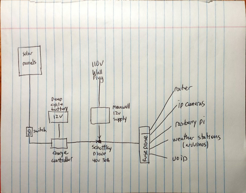
Can you post a diagram or a picture of how you connected the switch up to your panels and batteries?
Thanks.. Tom..
attached. hooking it back up will have to wait. i was suspecting the pads/contacts in the switch too, but given is rated for 30a and i tried two different switches, i didn't think it would be a damaged pad. in both cases, the screws for pos and net turned colour from the heat, but ground didn't, implying that the issue isn't a specific one off (as it happened on all 4 live contacts, but not the two ground contacts).
Hi,
Thanks, but that is not what we need.
You need to draw each wire in the circuit, so there will be two wires from the PV, positive and negative, the battery has two terminals, the charge controller has more than 2 two terminals.
The schottky has two terminals, where do the three wires you show, connect?
Where is gnd and battery positive?
OPs diag.
AWG14 is too thin, you are losing a low of power to I-squared-R losses. AWG is 2mm^2, consider
something more like 6mm^2.
The problem is you have a low voltage high current circuit so the wiring has to be very low
resistance to make losses negligible at 10A for a 60 foot run (there and back). I make it 160 milliohms
as you have it, so that you lose 1.6V to the wiring...
In general you don't want long power cables at low voltage, it means spending a lot of money on
copper!
Your switch is not rated for high current DC, note, although that isn't the cause of overheating, its
a risk of unquenched arcing.
The switch overheating sounds like you're shorted out something. Switches go in series, not across.
TomGeorge:
Hi,
Can you draw a diagram showing specifically hw you connected wires to the switch you tried.
Please label every wire and switch terminal.
Thanks.. Tom...
hopefully this helps. the load from devices never exceeds 4.7 amps
i wanted full disconnect, not just a switch on the positive line, hence the 3 pole switch.
the wire should be fine, hadn't though of voltage losses though. i still get a solid 13-14v at the charge controller in full sun. makes sense though, as a 12v panel should be a bit more than that in full sun.
when i was wiring it, all i was thinking about was amps, never though of voltage drop. might just pull a second run of 14 awg wire and split the panels between the two sets of wires. another day though!