I am going to start assembling a few components for a project am working on. I have bought a few things I think I need and I want to share with you.
My project has led lights that turn on when I press a button. It also activates a vibrator motor and play a sound. It is all powered by two 3.7v rechargeable cell coin batteries (charged via two small solar panels). Sometimes a button activates a specific sound (that's why the micro SD module) and the vibrator; another button will activate blinking led lights, and other button will run the vibrator, sound, and led lights at once, depends on the button pressed.
I may include also a battery level component.
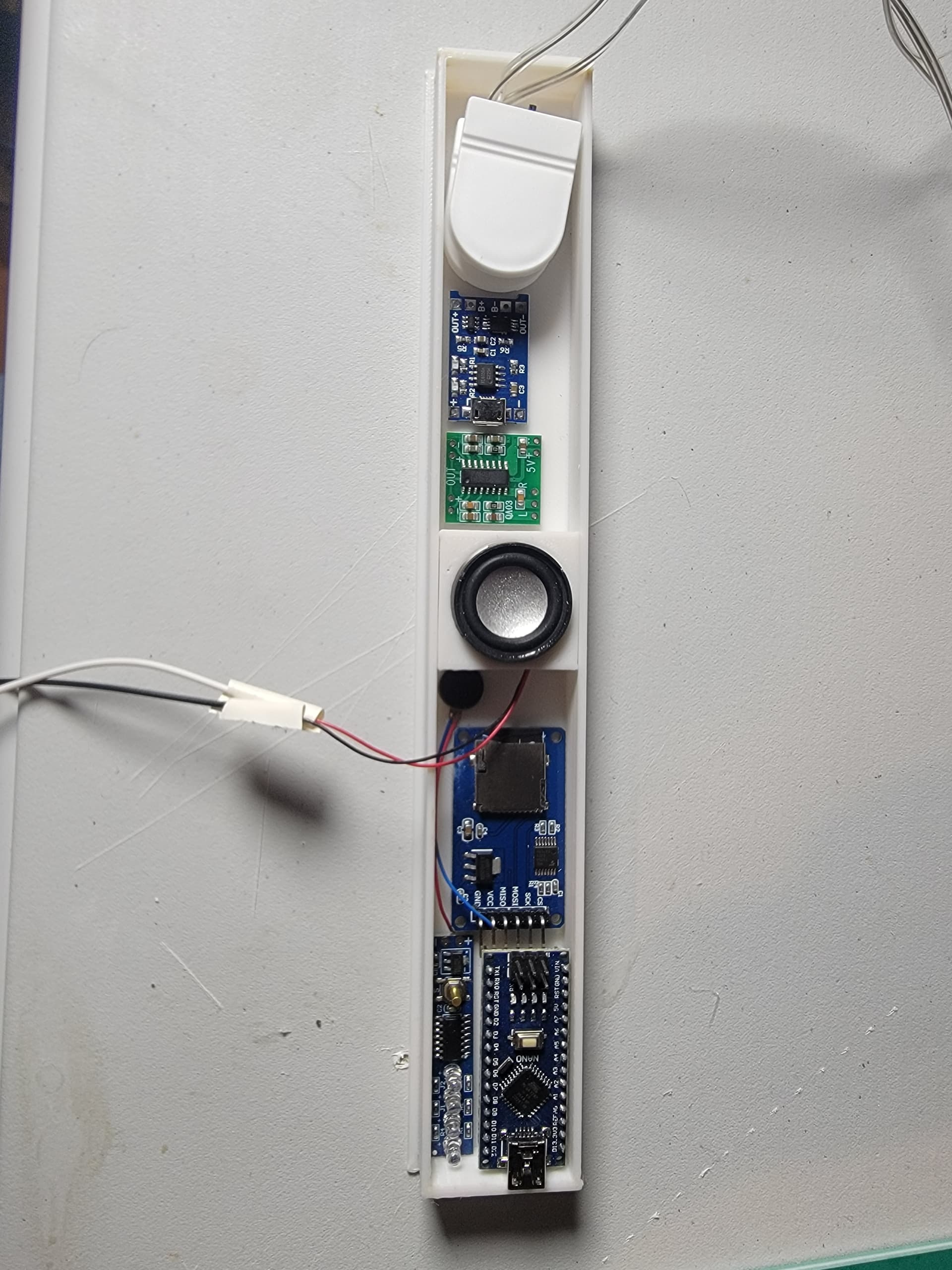
I'm attaching pictures of the components.
Can you advise me if these are the right ones or should I use different ones?
I have bought three different microprocessors. I am not 100% sure which one I'll be using in the end. Maybe the seeeduino with an extended slot. All and all I'll need to connect 7 buttons and 15 or 16 led lights.
Please describe the charging scheme you have in mind. What kind of batteries will be used?
Something to consider is that the solar cells, during the day generate power.
At night, the solar cell becomes a resistor and consumes power from the battery, unless the solar cell has a blocking diode. The blocking diode, I'd use a Schottky, will cause a V drop that will reduce the available Vbatt.
If a blocking diode is not used, there is risk of solar cell damage from the solar cells not being efficient resistors.
Thanks for the info. I'm actually going to use a battery charging module, but I'm not sure if it has a diode integrated.
Here is the description from Amazon:
Me, I do not have recommendations for buying any hardware for solar charging of Li batteries. I tried numerous Li solar solutions, they just do not work well.
I figure you're trying to make something small. With 5V solar cells you should get a 3.3V project that runs OK. 5V solar cells to a TP4056. Battery ( 3000mAh Li) connected to the TP4056. TP4056 output to a 3.3V LDO regulator, filter caps should provide power for a small project. It will not work in cold weather and will require regular battery replacement.
Me, I'd go a different route but it is not as compact as the above.
The charger module shown in the picture appears to be the standard TP4056 charger IC with additional protection circuitry. The TP4056 datasheet says no blocking diode is required. I have one of those modules, and measuring resistance from Bat+ back to In+, I see a capacitor charging, but no other current flow. So I suspect the blocking function is built into the module.
However, are your solar cells connected in parallel or in series? If parallel, they may need blocking diodes to prevent backfeeding from one cell to the other.
Well, using the batteries in series probably means you won't be able to use that charger module. The TP4056 is single-cell only, or at least parallel multi-cell.
As for making it work, I don't really know anything about what you're building. If at some point you draw up a schematic, you might post it here and see wht comments you get.


