I need to rotate a 7,5kg solar tracker assembly, and am wondering which motor speed reduction ratio would be suitable. There are many worm drive gears on offer, from 5:1 to 100:1, and probably other ratios, too. Another question would be if a brushed DC motor or DC stepper motor should be used. Basic principle below, it's about component (3).
The most important parameter ought to be the torque, that the motor manages to turn the equipment.
Speed is Your descision. At sunset the tracker can be moved to position of sunraise and be ready. All night available. And the sun doesn't move very fast....
Inevitably, it will have to somehow deal with some static and dynamic wind loads, but the location, large-ish back yards, have lots of fairly high shrubbery as wind breakers, and often some sheds, etc. It's not to go on an open field, or on top of a garage roof, or into a turbulence funnel between two homes.
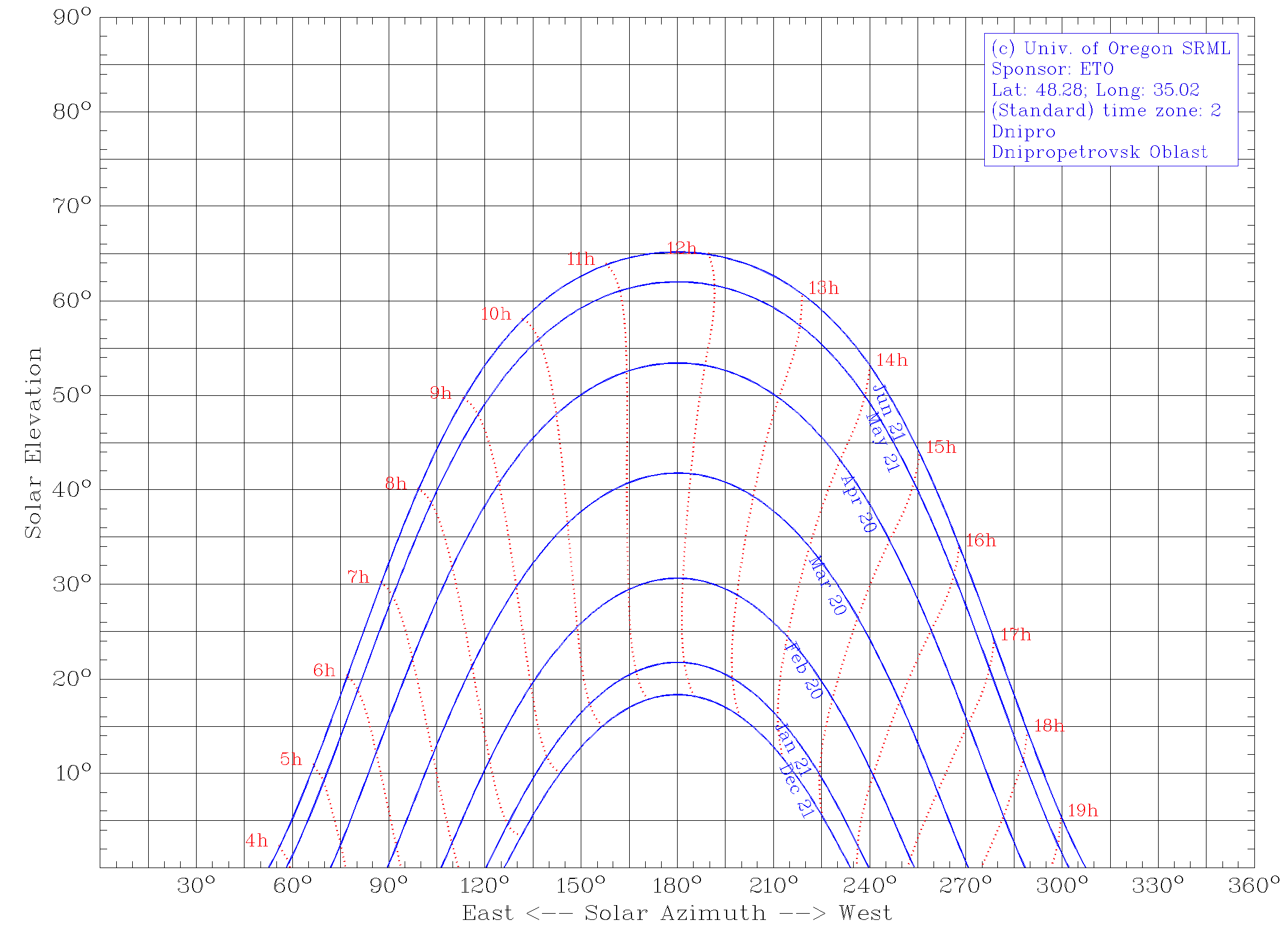
A program reliably calculates the sun's path, see below, and there is an Arduino library for that; but I based the solar tracker on the principle with one linear actuator shown above. The rotation scheme, night return and storm parking is to be based on an on/off schedule. Ideally, I want to compare near real-time vs. every hour tracking output, so the brushed DC motor or DC stepper motor reduction ratio needs to be suitable for both.
With that sort of system, you re just guessing that the position will be what you want. You need to design a system with actual position feedback so your program can ensure the position is correct.
For component 3 (azimuth rotation), a stepper motor is ideal. If the support is horizontal, the rotary table needs only to be aligned once to North (0 degrees, for example), and then calculate the number of steps to orient the assembly to any other azimuth.
Well, the motors I saw have encoders, just like the linear actuators. The question rather is which type of motor and what reduction ratio. Some researchers suggest a low ratio. Some researchers suggest a high ratio. For me, it is hard to judge who is right, or if it maybe doesn't even matter.
Thanks, a heliostat is more or less the same thing; that's a fun project!
So, you are using a ratio of 5:1. I have to contend with some wind and turbulence flutter. Do you think your geared solution based on a stepper motor, scaled up, would hold radial and axial loads as well as a worm geared solution?
I recommend going with the highest ratio you can that still allows you to move at the speed required. That'll reduce the torque required by your motor to a minimum. You'll have an easier time overcoming wind forces as well. The downside is that the motor will need to rotate for a longer period of time, but also at a reduced torque. How sensitive is your energy budget?
The azimuth speed, if the solar tracker were to follow the sun in real-time, would be 15° per hour so 0,000072721944444 rad/s. Regarding the energy budget, what I know is that the annual DNI is at best 1300 kWh/m2 (daily 3.6 kWh/m2), and the already donated 12V 100W rugged ETFE PV modules are 0.65 m2 and weigh 2.8kg.
You don't need an encoder with a properly designed stepper drive.
If the motor ever skips steps, the drive was not properly designed (or selected) for the task.
What is the solar tracker supposed to do? The requirements for positioning a PV panel or a telescope are completely different.
I've seen many times where maintenance techs will unhook a motor and then move an assembly knowing full well they're not supposed to. When it's powered back up the assembly needs to be homed to a known position assuming they don't crash it first. I personally prefer limit switches and absolute encoders because of people creating situations like this. OP might have full control and not be necessary though.
To position a solar panel and to maximise yield. How can I tell if a stepper motor drive is properly designed? Are some tell tale things to look for? Or is it only a function of price? Is this thing a bag o' shite, ok, or even good?
It has a max permissible output torque of 159.31lb-in.
How much does the panel weigh and what is the lever length between the rotation points in your drawing? The max force required under the most extreme conditions should be roughly 75% of the max torque spec.