So, my old soldering station broke down. It's the pot with switch that gave up. After some research I found out it is a common problem with this pot. It's cheap and mechanically bad engineered. After opening up the pot a piece of metal (wich was loose in the first place i could hear rattle around and feel it grinding when turning the temp controp knob) fell out.
So I was thinking to hardwire this soldering station and have it have just one temperature setting just like the cheap single wand irons.
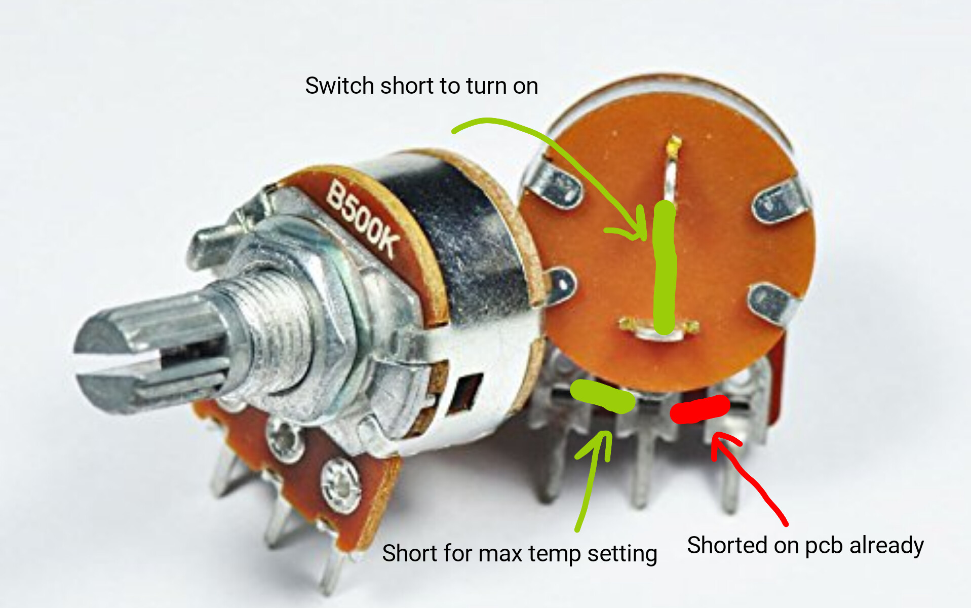
This is the potmeter that is inside.
The middle to pins on the backside are the switch. Two of the three legs are shorted. So my thought was to short the switchpins, and short the 2 pins with the 3th pin.
This way I would have the iron running on the highest temperature setting is that right? I know that I should not keep it running for a long time. It will also just be a backup soldering iron for quick work on bigger beefier cables.
Btw, I'm on the road living the no nomadic life in a van so ordering a new pot is way to much hassle.
Shorting so I have the max temperature since it will be used once in a while for the quick beefy wires, so high temperature and high wattage needed to get the job done.
Secondly, I can not measure the resistance since it is broken.
Install a switch for turning it on and off minimizing "on" time maybe a good idea.
Btw, I'm on the road living the nomadic life in a van so ordering a new pot is way to much hassle.
Thank you for thinking along with me I appreciate it.
This one is used for my 2.5mm2 wiring in my van and even thicker lipo battery leads. So it has always been on max temperature. Turn on, tinning, soldering, turn off. Prepare next leads, repeat.
Leo the clips you see were there to keep the cover on. The resistor part is "printed" on the inside of the cover. The slider to adjust the resistance attracted to the knob. This knob will not stay in place anymore. I guess the cheapo version.
So I shorted the switch part, as seen on the first picture. And shorted the pot legs seen on the second picture.
I'll get a switch in place of the short I have in the first picture if it works.
(Test tomorrow because its nighttime here and batterybank of van is not fly charged due to cloudy weather today)
Bringamosa:
Leo the clips you see were there to keep the cover on. The resistor part is "printed" on the inside of the cover. The slider to adjust the resistance attracted to the knob. This knob will not stay in place anymore.
I have opened a shipload of these type of pots.
The back wafer (which contains the switch) can be removed without affecting the rest of the pot.
Leo..
How does the knob stay in place, centred? There is a loose metal part that functions as te switch I guess, no idea how to get that back in place, but it also holds the shaft of the knob in place. The shaft of the pot is loose, and this cause the contacts on the inside to create a poor connection.
I tried to find a picture of the inside of my pot online but i cant find it. The pot in the first picture is a heavy dutier one. Will post pictures of the inside tomorrow.
The aluminium shaft is connected to the aluminium flange.
The four front lips of the shielding hold the front pertinax pot/track in place.
The four back lips hold the pertinax switch plate in place.
Just remove the pertinax back, and any broken pieces you find in there.
Leo..
The part circled in green was rattling... i think this is needed to keep pressure on the parts in the next two pictures to keep contact and regulate the resistance.
Just to be sure, in the picture above, the mains in needs to be on plug 1 and the soldering iron on plug 2 right? Forgot what cable went where and both plugs are the same.
When everything is connected without the part from the first picture and the switch shorted as the pictures in previous posts, I can not read any resisrrance between the legs of the pot. The multimeter shows OL. So this is the reason why I think the little metal part from the first picture is needed to get any regulated temperature.
So for now, with the switch shorted and the legs on pot shorted I do get a hot soldering iron, otherwise nothing.....
Well there we go, first, 2mb max per post. Fail..... Then 1mb max per picture. Fail. then link to shared Dropbox picture. Fail.
Where oh where are we here in this time on this forum, where you can not just upload a picture to keep your post and it gets resizes and embeds by itself.... How NOT to keerp your posts informative.
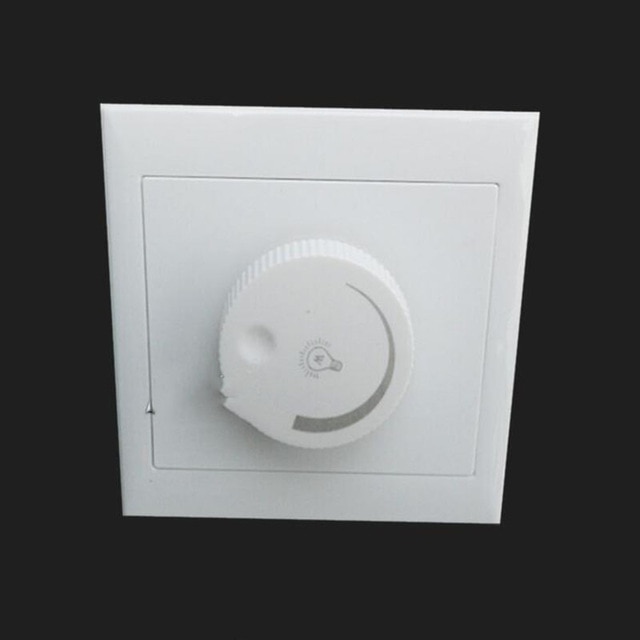
Anyways end of rant. I guess it will be hardwired switch and pot. And an online light switch dimmer
Why did you also undo the front tabs and remove the whole metal casing.
Just the back would have been enough to remove the broken parts of the switch.
If you put it all back, then you still can control the temp with the pot.
Just use a different switch next to the pot.
Plenty of 500kB replacement pots on ebay if you can't put it back together again.
Leo..
Leo, only thing missing in this pot right now is the little metal piece shown with the green marking. Nothing else.
Like i said before, cheapo version of this pot? i can not find any picture of this particular pot online so the first picture In the first post is for reference to show what legs are shorted.
Since I'm on the road in can not order one. My French is so good I can order a baguette, but I can not ask around for local electronics shops.
Also atm I do not have proper tools to solder and desolder a new pot, what you see there in the pictures is a hackjob to get it going again.
You just had to remove the BACK of the pot (with the two switch terminals) to get the loose bits out.
And then put it back (folding the tabs back).
And shorted the two switch wires, to turn the iron permanently 'on'.
5-minute job, turned into a nightmare.
Leo..
Leo there is no back of the pot. The two switch terminals are soldered into the pcb. The body is soldered right in the pcb. The pcb is the back part in this case.
The metal part fell out after opening it up. That part was lose in the first place.