I have a circuit that drives a solenoid valve coil that is 33 ohms and 24 volt.
It has a PNP transistor, with two 1 ohm resistors. One on the emitter and one between the collector and ground. Anyone know what they are there for?
I want to use the arduino and PWM with a mosfet to drive the coil, but these two resistors on the original circuit has me a tad bit nervous because of the 1 ohm resistors that I don't understand.
The coils on the valve are fine. The old circuit that used to drive them is what is toast. They are proportional, and I'm guessing they used PWM to drive them. The issue is the old circuit that used to drive them. The resistors appear to be setup as a voltage divider, but the voltage is 24 on the board, and the coils are 24, so why would it have a voltage divider, if that's what it is.
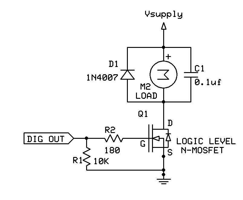
Remove them, along with the other bits. This circuit will work to activate the solenoid (M2 is the coil, the capacitor is not needed, but the diode D1 is absolutely required):
Thanks. I built a circuit to drive coils that are 33 ohms (not the ones on the machine, just to test) and it works nice. The question I have is what the 1 ohm resistors are for. My concern is that the original manufacturer put them there for a reason. The resistors had to cost a little bit, times how many machines they made. If I drive the actual coils on the valve and everything works nice.... will it fry sooner or later because I didn't use the 1 ohm resistors with the mosfet? There has to be a reason they are there on the original circuit, and it sure would ease my mind to know why they are there.
Your text with the 1ohm resistor connected to the collector of a PNP transistor doesn't make sense. Could you draw a diagram and upload a picture of the solenoid/transistor/wiring.
Leo..
I don't know either, and as mentioned above, your description of the circuit doesn't make sense to me. There should be a resistor connected to the base of the PNP transistor, to limit the base current. Check the transistor type, data sheet and pin arrangement, as you may have misidentified the leads.
You should have no problems with the circuit posted in reply #6.
The circuit you posted is almost identical to the one I built and tested. It works with some test coils, in fact it works great. I really happy with the circuit I built. The thing is, the original circuit that controlled these coils has these mystery resistors on a PNP transistor. I'm using a mosfet, and it works great. My concern is why these resistors are there, and if my circuit, much like the one you posted, will cause some issue that I don't foresee by not having these mystery resistors in the circuit. I'm going to draw it up and post it here in a little bit..
There must be more to it.
The solenoid has no kick-back diode, which will eventually kill the transistor. The base could have added parts, to make it a constant current source (which requires an emitter resistor). The resistor to ground could be for a test point, to measure/check coil current.
Leo..
Yes, there is a whole bunch more it this circuit board then what I have drawn out. I'm not sure how a person could ever follow all the leads even if it was a one sided board. This is a two sided board. I thought that the output from the transistor would be enough.
There are massive diodes that protect the circuit, I could redraw the circuit with them, but I don't think that would help as we all use them and know where they belong.
The four transistors are left-fwd/rev and right=fwd/rev to move the machine. Two voltage regulators (7815) are on the left.
The 2SA1452 transistors are indeed PNP. Why do you want to include an Arduino. Do you want to replace that board with an Arduino, or have the Arduino also control the solenoid. If so, then you can use a P-channel mosfet across the existing PNP transistor. Fourth diagram here.
Leo..