(Solved) Attiny85 SOIC-8 20U impossible to program

OK, same problem, different error messages. No way someone has reprogrammed these. This is a brand new piece of cut tape, all labelled
ATMEL 20U
ATTINY85
2320BJV

I bought 40 of them from an Ebay seller with a stellar reputation. Here's my verbose output:

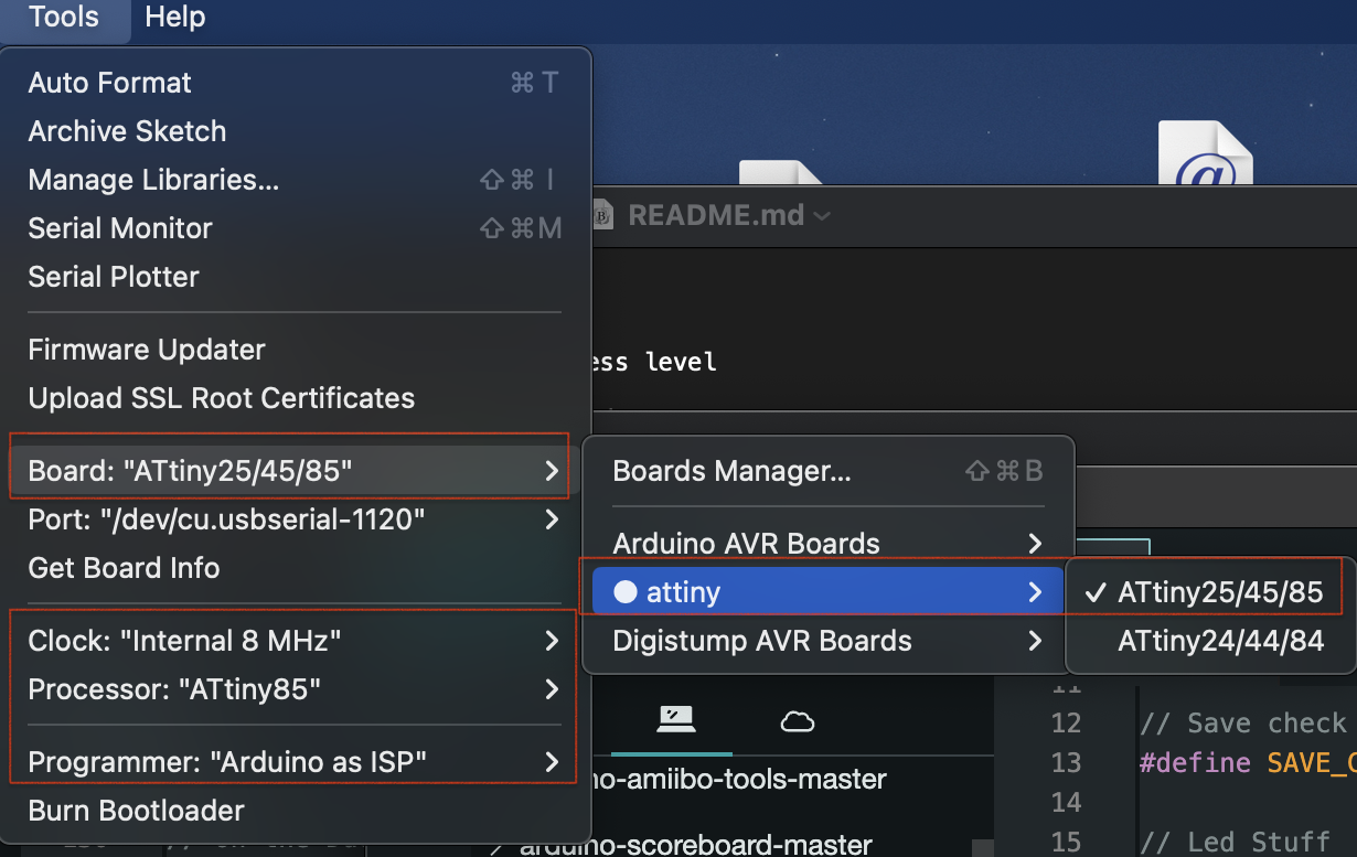
Arduino: 1.8.13 (Windows 10), Board: "ATtiny25/45/85, Disabled, CPU, ATtiny85, 8 MHz (internal), EEPROM retained, B.O.D. Disabled"
Sketch uses 2418 bytes (29%) of program storage space. Maximum is 8192 bytes.
Global variables use 36 bytes (7%) of dynamic memory, leaving 476 bytes for local variables. Maximum is 512 bytes.
C:\Users\kjmclark\AppData\Local\Arduino15\packages\arduino\tools\avrdude\6.3.0-arduino17/bin/avrdude -CC:\Users\kjmclark\Documents\Arduino\hardware\ATTinyCore-master\avr/avrdude.conf -v -pattiny85 -cusbtiny -Uflash:w:C:\Users\kjmclark\AppData\Local\Temp\arduino_build_629908/Hunting_PIR_sensor_with_433mhz_3a.ino.hex:i 

avrdude: Version 6.3-20190619
         Copyright (c) 2000-2005 Brian Dean, http://www.bdmicro.com/
         Copyright (c) 2007-2014 Joerg Wunsch

         System wide configuration file is "C:\Users\kjmclark\Documents\Arduino\hardware\ATTinyCore-master\avr/avrdude.conf"

         Using Port                    : usb
         Using Programmer              : usbtiny
         Setting bit clk period        : 5.0
avrdude: usbdev_open(): Found USBtinyISP, bus:device: bus-0:\\.\libusb0-0001--0x1781-0x0c9f
         AVR Part                      : ATtiny85
         Chip Erase delay              : 400000 us
         PAGEL                         : P00
         BS2                           : P00
         RESET disposition             : possible i/o
         RETRY pulse                   : SCK
         serial program mode           : yes
         parallel program mode         : yes
         Timeout                       : 200
         StabDelay                     : 100
         CmdexeDelay                   : 25
         SyncLoops                     : 32
         ByteDelay                     : 0
         PollIndex                     : 3
         PollValue                     : 0x53
         Memory Detail                 :

                                  Block Poll               Page                       Polled
           Memory Type Mode Delay Size  Indx Paged  Size   Size #Pages MinW  MaxW   ReadBack
           ----------- ---- ----- ----- ---- ------ ------ ---- ------ ----- ----- ---------
           eeprom        65    12     4    0 no        512    4      0  4000  4500 0xff 0xff
           flash         65    12    32    0 yes      8192   64    128 30000 30000 0xff 0xff
           signature      0     0     0    0 no          3    0      0     0     0 0x00 0x00
           lock           0     0     0    0 no          1    0      0  9000  9000 0x00 0x00
           lfuse          0     0     0    0 no          1    0      0  9000  9000 0x00 0x00
           hfuse          0     0     0    0 no          1    0      0  9000  9000 0x00 0x00
           efuse          0     0     0    0 no          1    0      0  9000  9000 0x00 0x00
           calibration    0     0     0    0 no          2    0      0     0     0 0x00 0x00

         Programmer Type : USBtiny
         Description     : USBtiny simple USB programmer, http://www.ladyada.net/make/usbtinyisp/
avrdude: programmer operation not supported

avrdude: Setting SCK period to 5 usec
avrdude: initialization failed, rc=-1
         Double check connections and try again, or use -F to override
         this check.


avrdude done.  Thank you.

An error occurred while uploading the sketch
Invalid library found in C:\Users\kjmclark\Documents\Arduino\libraries\ArduinoCore-mbed-master: no headers files (.h) found in C:\Users\kjmclark\Documents\Arduino\libraries\ArduinoCore-mbed-master

This report would have more information with
"Show verbose output during compilation"
option enabled in File -> Preferences.

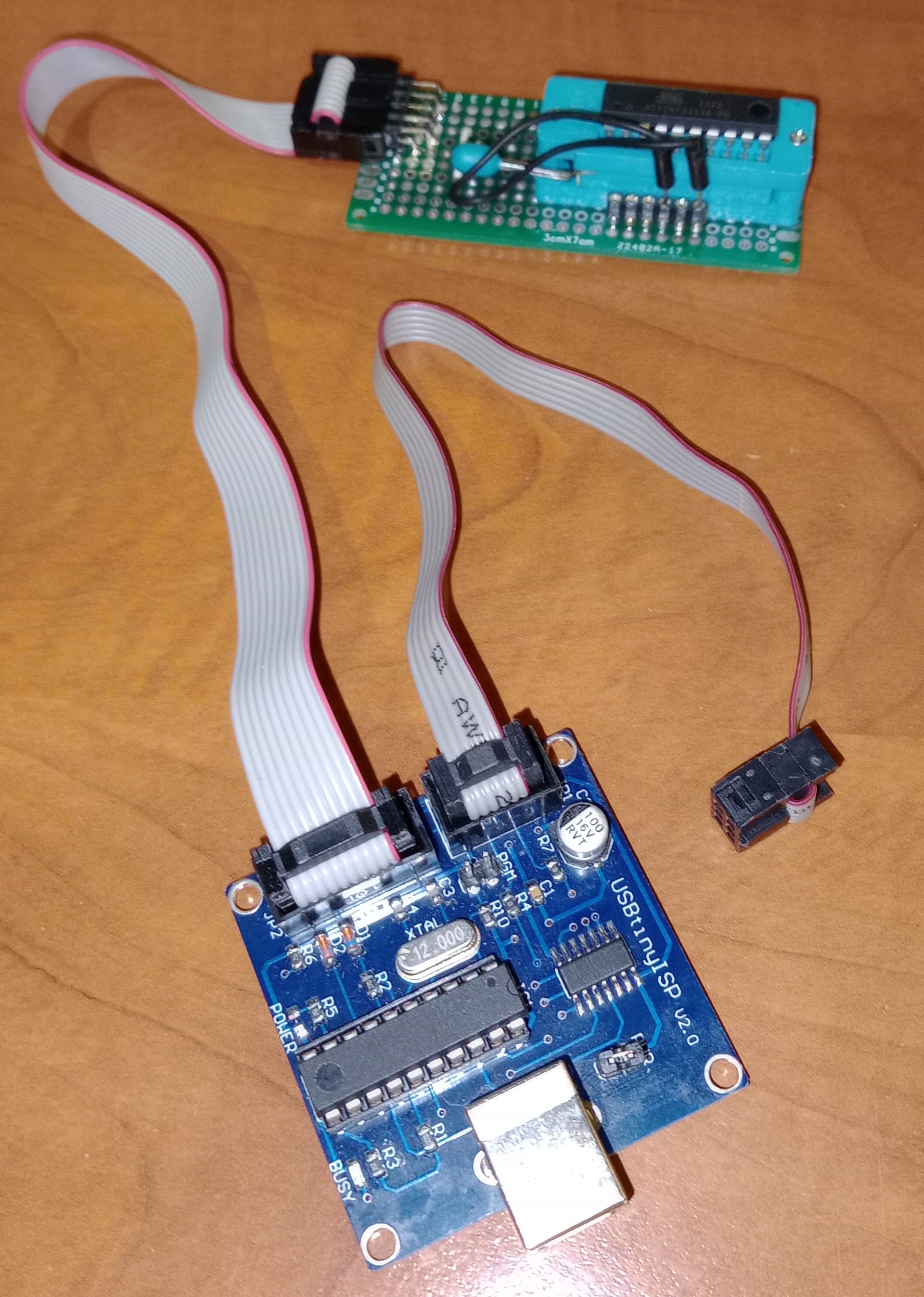
The programmer is a Sparkfun programmer board that works great. The weird thing is that I just - like two minutes before - programmed another set of cut tape ATTiny85s with no problems (different seller and time frame - the 40 are new, the other cut tape is from a couple years ago). Opened the second tape, put an ATTiny in the same ZIF board Kayumba used, and I get errors. Grabbed the second ATTiny from that (2nd) tape, and it does the same thing.

Seems kind of weird that I'd need an HV programmer for brand-new, un-opened tape, ATTiny85s, doesn't it?

You wish.

"Top-chips - 97.7% positive feedback, 86k items sold". Dunno, that's pretty good. 86 thousand transactions and 98% of them were positive. I've had bad transactions with Digikey and Mouser - mostly good, but not all of them. Cut tape is cut tape is cut tape, usually.

For several very good reasons, I do not believe "customer ratings", especially on sites like eBay and Amazon.

I also note that you aren't having much luck with your purchases.

1 Like

I also bought Attinies from Aliexpress or Ebay and that's in fact the reason I had to build an HV programmer.

I suspect that manufacturers sometimes buy or stock the AT85 preprogrammed, if their PCB design does not allow for ISP programming after the board is produced. Quite likely with a T85, as you need 4 pins for programming already.
I cannot imagine they store them just in a bag as the PCB placing machine needs a reel.
Now what to do with the surplus? Toss it away, or make an extra buck and sell the reel to an Ebay seller? The chips are genuine and have never been soldered on a board. So from a HW perspective they are new.

However, you may need to kiss them awake with an HV programmer, or try if they respond when connecting an (8MHz) crystal to it or an external clock signal.

If for whatever reason they are clocked from their internal 128KHz watchdog timer oscillator you may have a chance with Avrdudess.

I tested a bit here with a T85 clocked at 128KHz and if I set the bit clock in Avrdudess to 1500 my USBTiny can talk to it in about 25% of the efforts. So after 15 times clicking on "write" fuses I was able to set the fuses back to their default.
My USBASP programmer can talk to it 100%, but that's not what you have I understand.

2 Likes

So why didn't I buy these at Digikey, like I normally would? Because they had none. Zero. I just went back and checked, and yeah, they have some now, but at the time they had none at all. And actually, for the SOIC8 ATTiny85s they have now, Digikey has not verified that they're programmable (they have a parameter for that). So, you could well end up with the same cut tape ATTiny's and find they're not directly programmable either. I suspect Hmeijdam is right, and they're excess from someone's bulk purchase.

I rigged up a high voltage programmer for these, and nothing. Darned thing just lights the LED and does nothing else. Now, either I've wired the programmer wrong, which I'll quadruple check, or I need to rig up an external timing signal. I don't keep crystals lying around.

Please, post the photograph of the Programmr that you drive by the posted Interface (AVRDUEDESS). I use the same Interface to drive the following Programmer. I don't need to click on write command for so many times to set/clear the fuse bits.
image

I used this antique USBTinyISP programmer based on a Attiny2313. The ZIF socket is homemade and can have ATTiny85, Attiny13 and Attiny2313.

I hardly ever use it and the processor gets quite hot when it is on for some time. I always use USBASP sticks.

1 Like

This is the sketch I have in my HV programmer in the picture. You could give it a try if you like.

// AVR High-voltage Serial Programmer
// Originally created by Paul Willoughby 03/20/2010
// http://www.rickety.us/2010/03/arduino-avr-high-voltage-serial-programmer/
// Inspired by Jeff Keyzer http://mightyohm.com
// Serial Programming routines from ATtiny25/45/85 datasheet

// Desired fuse configuration
#define  HFUSE  0xDF   // Defaults for ATtiny25/45/85
#define  LFUSE  0x62   


#define  RST      8    // Output to level shifter for !RESET from transistor to Pin 1
#define  CLKOUT  13    // Connect to Serial Clock Input (SCI) Pin 2
#define  DATAIN  11    // Connect to Serial Data Output (SDO) Pin 7
#define  INSTOUT 10    // Connect to Serial Instruction Input (SII) Pin 6
#define  DATAOUT  9    // Connect to Serial Data Input (SDI) Pin 5 
#define  VCC     12    // Connect to VCC Pin 8


int inByte = 0;         // incoming serial byte Computer
int inData = 0;         // incoming serial byte AVR

void setup()
{
  // Set up control lines for HV parallel programming
  pinMode(VCC, OUTPUT);
  pinMode(RST, OUTPUT);
  pinMode(DATAOUT, OUTPUT);
  pinMode(INSTOUT, OUTPUT);
  pinMode(CLKOUT, OUTPUT);
  pinMode(DATAIN, OUTPUT);  // configured as input when in programming mode
  
  // Initialize output pins as needed
  digitalWrite(RST, HIGH);  // Level shifter is inverting, this shuts off 12V
  
  // start serial port at 9600 bps:
  Serial.begin(9600);
  
  establishContact();  // send a byte to establish contact until receiver responds 
  
}


void loop()
{
  // if we get a valid byte, run:
  if (Serial.available() > 0) {
    // get incoming byte:
    inByte = Serial.read();
    Serial.println(byte(inByte));
    Serial.println("Entering programming Mode\n");

    // Initialize pins to enter programming mode
    pinMode(DATAIN, OUTPUT);  //Temporary
    digitalWrite(DATAOUT, LOW);
    digitalWrite(INSTOUT, LOW);
    digitalWrite(DATAIN, LOW);
    digitalWrite(RST, HIGH);  // Level shifter is inverting, this shuts off 12V
    
    // Enter High-voltage Serial programming mode
    digitalWrite(VCC, HIGH);  // Apply VCC to start programming process
    delayMicroseconds(20);
    digitalWrite(RST, LOW);   //Turn on 12v
    delayMicroseconds(10);
    pinMode(DATAIN, INPUT);   //Release DATAIN
    delayMicroseconds(300);
    
    //Programming mode
    
    readFuses();
    
    //Write hfuse
    Serial.println("Writing hfuse");
    shiftOut2(DATAOUT, INSTOUT, CLKOUT, MSBFIRST, 0x40, 0x4C);
    shiftOut2(DATAOUT, INSTOUT, CLKOUT, MSBFIRST, HFUSE, 0x2C);
    shiftOut2(DATAOUT, INSTOUT, CLKOUT, MSBFIRST, 0x00, 0x74);
    shiftOut2(DATAOUT, INSTOUT, CLKOUT, MSBFIRST, 0x00, 0x7C);
    
    //Write lfuse
    Serial.println("Writing lfuse\n");
    shiftOut2(DATAOUT, INSTOUT, CLKOUT, MSBFIRST, 0x40, 0x4C);
    shiftOut2(DATAOUT, INSTOUT, CLKOUT, MSBFIRST, LFUSE, 0x2C);
    shiftOut2(DATAOUT, INSTOUT, CLKOUT, MSBFIRST, 0x00, 0x64);
    shiftOut2(DATAOUT, INSTOUT, CLKOUT, MSBFIRST, 0x00, 0x6C);

    readFuses();    
    
    Serial.println("Exiting programming Mode\n");
    digitalWrite(CLKOUT, LOW);
    digitalWrite(VCC, LOW);
    digitalWrite(RST, HIGH);   //Turn off 12v
  }
}


void establishContact() {
  while (Serial.available() <= 0) {
    Serial.println("Enter a character to continue");   // send an initial string
    delay(1000);
  }
}

int shiftOut2(uint8_t dataPin, uint8_t dataPin1, uint8_t clockPin, uint8_t bitOrder, byte val, byte val1)
{
	int i;
        int inBits = 0;
        //Wait until DATAIN goes high
        while (!digitalRead(DATAIN));
        
        //Start bit
        digitalWrite(DATAOUT, LOW);
        digitalWrite(INSTOUT, LOW);
        digitalWrite(clockPin, HIGH);
  	digitalWrite(clockPin, LOW);
        
	for (i = 0; i < 8; i++)  {
                
		if (bitOrder == LSBFIRST) {
			digitalWrite(dataPin, !!(val & (1 << i)));
                        digitalWrite(dataPin1, !!(val1 & (1 << i)));
                }
		else {
			digitalWrite(dataPin, !!(val & (1 << (7 - i))));
                        digitalWrite(dataPin1, !!(val1 & (1 << (7 - i))));
                }
                inBits <<=1;
                inBits |= digitalRead(DATAIN);
                digitalWrite(clockPin, HIGH);
		digitalWrite(clockPin, LOW);
                
	}

        
        //End bits
        digitalWrite(DATAOUT, LOW);
        digitalWrite(INSTOUT, LOW);
        digitalWrite(clockPin, HIGH);
        digitalWrite(clockPin, LOW);
        digitalWrite(clockPin, HIGH);
        digitalWrite(clockPin, LOW);
        
        return inBits;
}

void readFuses(){
     //Read lfuse
    shiftOut2(DATAOUT, INSTOUT, CLKOUT, MSBFIRST, 0x04, 0x4C);
    shiftOut2(DATAOUT, INSTOUT, CLKOUT, MSBFIRST, 0x00, 0x68);
    inData = shiftOut2(DATAOUT, INSTOUT, CLKOUT, MSBFIRST, 0x00, 0x6C);
    Serial.print("lfuse reads as ");
    Serial.println(inData, HEX);
    
    //Read hfuse
    shiftOut2(DATAOUT, INSTOUT, CLKOUT, MSBFIRST, 0x04, 0x4C);
    shiftOut2(DATAOUT, INSTOUT, CLKOUT, MSBFIRST, 0x00, 0x7A);
    inData = shiftOut2(DATAOUT, INSTOUT, CLKOUT, MSBFIRST, 0x00, 0x7E);
    Serial.print("hfuse reads as ");
    Serial.println(inData, HEX);
    
    //Read efuse
    shiftOut2(DATAOUT, INSTOUT, CLKOUT, MSBFIRST, 0x04, 0x4C);
    shiftOut2(DATAOUT, INSTOUT, CLKOUT, MSBFIRST, 0x00, 0x6A);
    inData = shiftOut2(DATAOUT, INSTOUT, CLKOUT, MSBFIRST, 0x00, 0x6E);
    Serial.print("efuse reads as ");
    Serial.println(inData, HEX);
    Serial.println(); 
}

If you don't close the serial monitor right after programming, but scroll up, you will see the values the fuses had before reprogramming to defaults.

2 Likes

I tried to use the AT85 to AT85 HV programmer from here: ATtiny85 Powered High Voltage AVR Programmer - Hackster.io. No joy with that, but it'd be no surprise if it was just a wiring fault. I disassembled that already, because then I tried the board and code discussed here: https://www.youtube.com/watch?v=yAT_TdD6nL0. That brought joy. Sure enough, these are pre-programmed ATTiny85s, with the reset pin programmed as I/O.

For people coming later, don't be shocked if cut tape ATTiny85s won't program, just find a good (from my experience Uno-based) high voltage programmer.

1 Like

Now that you got a happy ending (as happy it can be), don't forget to give creds to those in this thread who deserve it (likes and flag one post as Solution).

Cheers!

Note that since various vendors and manufacturers (including Microchip themselves) offer a programming service that will deliver you pre-programmed (with your code) microcontrollers on tape, receiving parts on T&R is not a reliable indication that the chips have not been programmed.

1 Like

I fear some poor lad in the east just lost his day-job of opening those reels, resetting them with his HV programmer and toss them in a plastic bag. At least that's how I received them in the past.
Now they start skipping the HV reset phase.

Actually, it isn't my thread. But I have done likes on various posts here. Doesn't look like I can choose a solution, since I didn't start it. If I could, I'd have to pick between hmeijdam's several excellent comments, and add in that last one of westfw's for a nod too. Both of them pointed out the problem that programmable chips sometimes get programmed at the factory with pin 1 disabled for reset. I got my actual solution elsewhere, but I expect hmeijdam's version would have worked.

Thanks to most of you for the help!

I didn't check. This is one of the reasons why you should start a new thread.

Nevertheless, happy creating with the ATtinys! :cowboy_hat_face:

Not at all! Distributors will always package their pre-programmed devices just the way you want them. Someone has had the chips programmed and then put into tape for their pick-and-place machine. You got the left-overs from the production run. Also quite common.

Hi to everyone !
I resolve my problem.
I got it!
Now it works fine with all of my SOIC and DIP Attiny85 !

The mistake was "electrolytic capacitor" that I keep it onto my Arduino UNO board.
This capacitor shouldn't be here when you need to "prepare" the Arduino for the fist time by uploading the ISP sketch to it.

attiny_programming_w_arduino_uno 2
So, the reason of this "error" was my Arduino UNO that wasn't be prepared correctly before.

So here is how to do exactly :

1- Before all = > Prepare your Arduino UNO to be able to flash Attiny85.
Attention, Arduino UNO "reset" pin have to be without any capacitor.

  • Go and select: Tools/Board/Arduino AVR boars/Arduino UNO
  • Go and select: Tools/Board/ Programmer/Arduino as ISP

Capture d’écran 2023-11-11 à 22 30 50

  • Go and select: File/Exemples/11.ArduinolSP/ArduinoISP

Capture d’écran 2023-11-11 à 22 32 13

  • Upload ArduinoISP Exemple Code by clicking to "upload" button

Capture d’écran 2023-11-11 à 22 34 19

Done! Arduino are almost ready.

Now you can configure your Arduino UNO pinout for flashing Attiny85.
attiny_programming_w_arduino_uno

2 - Install Attiny boards manager by David A. Mellis

Capture d’écran 2023-11-11 à 22 36 51

  • Go to : Tools/Board/Boards Manager/
  • in search line type "attiny" and find "attiny by David A. Mellisby"

Capture d’écran 2023-11-11 à 22 35 48

  • Install it

3-Prepare Arduino UNO to flash Attiny85:

  • Go and select : Tools/Board/attiny/ATtiny25/45/85
  • Go and select : Tools/Clock: "Internal 8 MHz"
  • Go and select : Tools/Processor: "ATtiny85"
  • Go and select : Tools/Programmer: "Arduino as ISP"

Capture d’écran 2023-11-11 à 22 38 56

  • Go to : Tools/Burn Bootloader

Capture d’écran 2023-11-11 à 22 42 03

4-Flash sketch into Attiny85:

  • Open sketch if it not done before.
  • Go to "Sketch" and select "Upload Using Programmer"

Capture d’écran 2023-11-11 à 22 42 55

DONE !

Now,
Once your Arduino UNO are prepared and ready for flashing any Attiny.
All what you have to do !!! For each Attiny85 !!! , is :

  • Go and select : Tools/Burn Bootloader
  • Open sketch (if it not done before).
  • Go to "Sketch" and select "Upload Using Programmer"

Voilà :crazy_face:

Thanks for all community :smiling_face_with_three_hearts:

1 Like

This topic was automatically closed 180 days after the last reply. New replies are no longer allowed.