After creating a working prototype with DIP Atmega328 chip/ arduino uno I recently got PCBs assembled with SMD components and Atmega328p TQFP soldered onto them, but now I'm having a hard time trying to upload the arduino program.
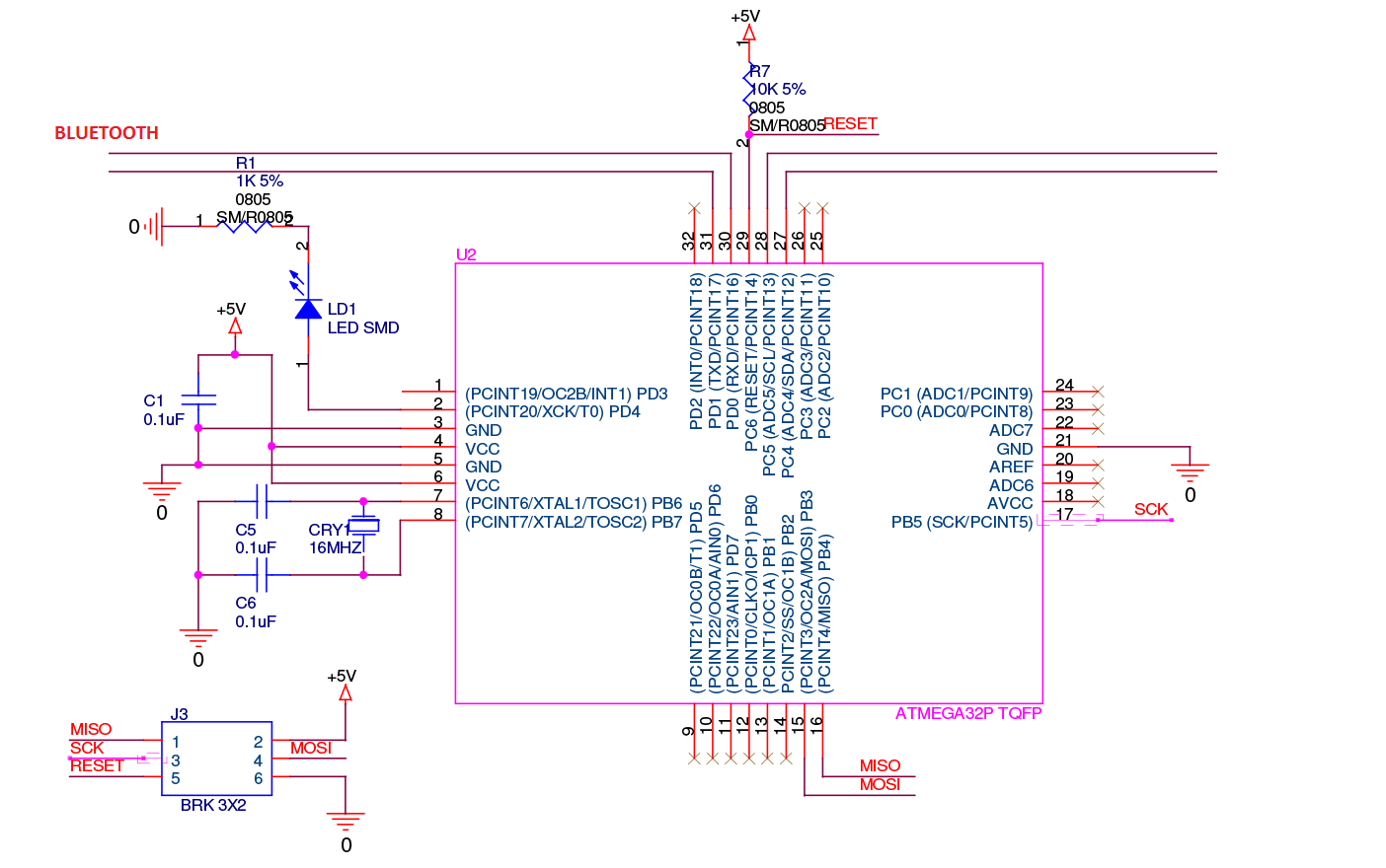
This is the schematic of the PCB with Atmega328p TQFP with ISP headers for programming:

I'm using usbasp programmer with upgraded firmware to upload the code. The chip gets detected and also I can upload sketches to it but the problem is the code runs slow, which I found out is due to the default 8MHz internal clock.(the blink program makes LED blink every 16 seconds instead of 1 second,i.e. with delay(1000))
Now to switch to the external 16MHz clock which I want to use I found out [here][2] that I have to change the fuse values from the default
lfuse: 0x62 hfuse: 0xD9 efuse: 0x3F
to
lfuse: 0xFF hfuse: 0xDE efuse: 0x05
I tried it two times and both the times it screwed up the Atmega328p chip
C:\Users\p>avrdude -p m328p -c usbasp -U lfuse:w:0xFF:m -U hfuse:w:0xDE:m -U efu
    se:w:0x05:m

    avrdude: AVR device initialized and ready to accept instructions

    Reading | ################################################## | 100% 0.03s

    avrdude: Device signature = 0x1e950f
    avrdude: reading input file "0xFF"
    avrdude: writing lfuse (1 bytes):

    Writing | ################################################## | 100% 0.02s

    avrdude: 1 bytes of lfuse written
    avrdude: verifying lfuse memory against 0xFF:
    avrdude: load data lfuse data from input file 0xFF:
    avrdude: input file 0xFF contains 1 bytes
    avrdude: reading on-chip lfuse data:

    Reading | ################################################## | 100% 0.01s

    avrdude: verifying ...
    avrdude: 1 bytes of lfuse verified
    avrdude: reading input file "0xDE"
    avrdude: writing hfuse (1 bytes):

    Writing | ################################################## | 100% 0.03s

    avrdude: 1 bytes of hfuse written
    avrdude: verifying hfuse memory against 0xDE:
    avrdude: load data hfuse data from input file 0xDE:
    avrdude: input file 0xDE contains 1 bytes
    avrdude: reading on-chip hfuse data:

    Reading | ################################################## | 100% 0.01s

    avrdude: verifying ...
    avrdude: 1 bytes of hfuse verified
    avrdude: reading input file "0x05"
    avrdude: writing efuse (1 bytes):

    Writing | ################################################## | 100% 0.03s

    avrdude: 1 bytes of efuse written
    avrdude: verifying efuse memory against 0x05:
    avrdude: load data efuse data from input file 0x05:
    avrdude: input file 0x05 contains 1 bytes
    avrdude: reading on-chip efuse data:

    Reading | ################################################## | 100% 0.01s

    avrdude: verifying ...
    avrdude: 1 bytes of efuse verified

    avrdude: safemode: Fuses OK

    avrdude done.  Thank you.


    C:\Users\p>avrdude -p m328p -c usbasp

    avrdude: error: programm enable: target doesn't answer. 1
    avrdude: initialization failed, rc=-1
             Double check connections and try again, or use -F to override
             this check.


    avrdude done.  Thank you.
Both of the PCBs are not responding to the usbasp programmer and now I have only got one PCB left. I desperately want to get the final one working.

This is my first time using the SMD Atmega328p chips and any help would be appreciated.