Well let me first start with a question i have.
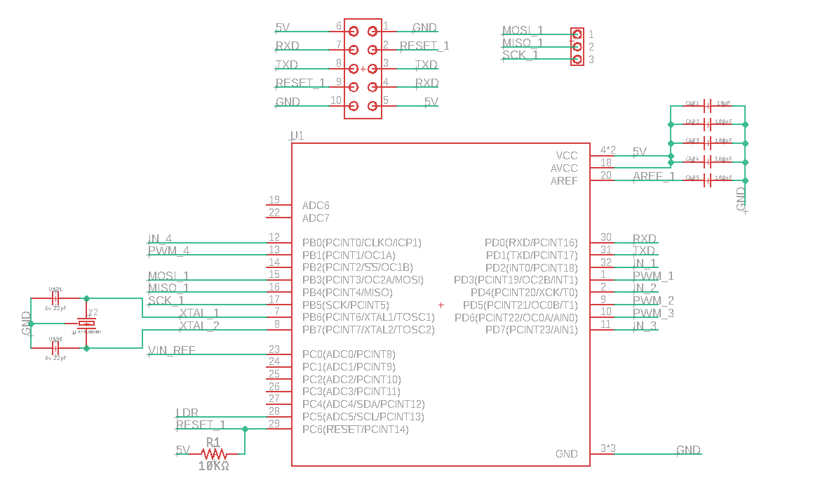
I have made a dedicated controller pcb based on the Arduino Nano V3 setup (The Atmega 328P-AU version).
After let it being send to me fully assembled and received correctly, i came across a problem that occurred.
I had made a mistake in the BOM file, where i gave up the Atmega328PB-AU instead of the Atmega328P-AU version.
Well after some testing, the Atmega328PB came out to not be working properly because of my external clock which walks out of sync for the pb version to understand.
I ran across much posts on the internet that were talking about this, but could'nt find any solution yet.
Now my question is, what would be a working and tested circuit and what component parts are listed for it to reach that point?
I have used the following components for it:
Crystal => LFXTAL027945
Caps => CBR06C220J5GACAUTO
To notice, this circuit works with the Atmega328P-AU Version.
But not with the Atmega328PB-AU version
Well it seemed like an drawing fault in my pcb design.
I've just made sure that the caps and crystal are close / around same distance to the crystal.
And i've made a change to make sure that the crystal and its caps are closer to the pcb.
Now even the Atmega328PB works like a charm.
So i've found my solution (google were my friend after +/- 24 hours of research), but i couldn't descripe my problem properly for you guys to understand.
This is my fault because i didnt find the good words for it.
Btw, if anyone has the same problem of bricking every chip after flashing the bootloader.
Just make sure that the caps and crystals are equally to the Atmega chip and make sure its very close to the chip aswell.
Thanks for your guys help, as always this forum is very supportive!
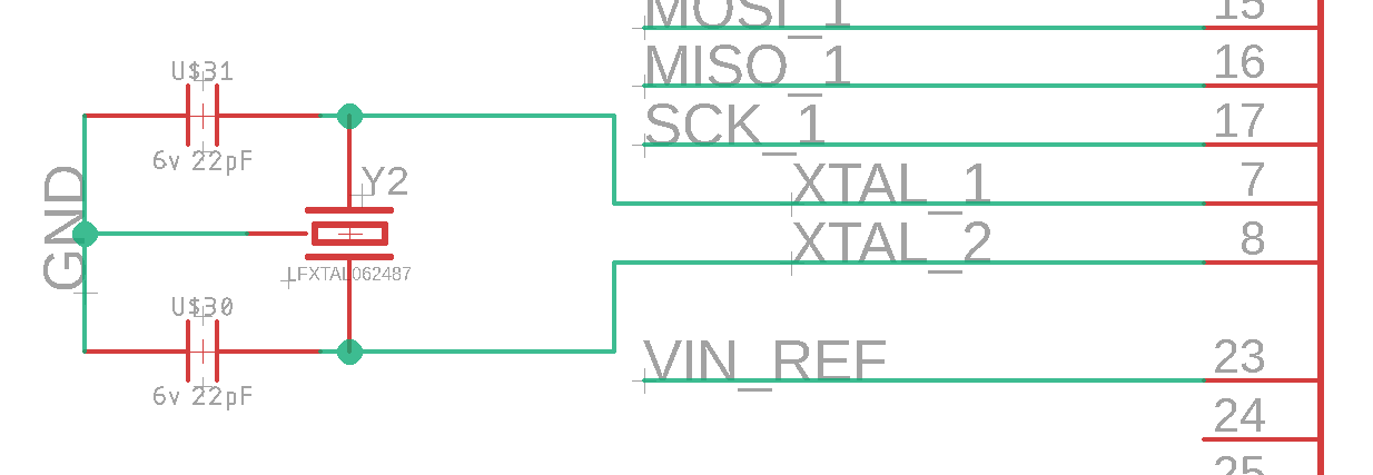
It were this crystal: LFXTAL062487. but the schematic does show my custom package where there are 2 pads connected to the GND pin in schematic. this means that there indeed 4 connected on the pcb. 2 to ground and the other 2 to the crystal pins of the atmega328pb with the needed caps.