[SOLVED] DS18B20 not working reliably on Nano ESP32

Hi all,

I've a strange problem with using two DS18B20 sensors on the Nano ESP32. I'm using the following circuit (the buzzer is not connected atm):

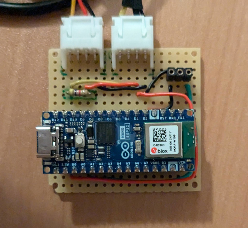
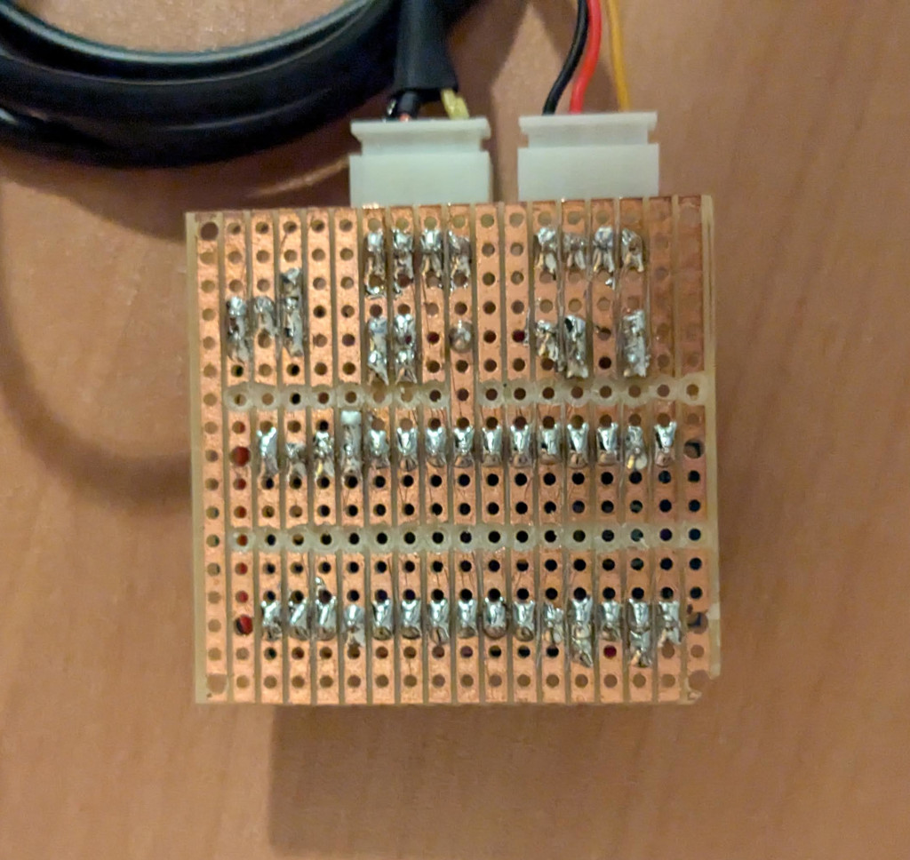
And here are some pictures of my board:

Finally, this is a minimal version of my sketch (adopted from ESP32 DS18B20 Temperature Sensor with Arduino IDE (Single, Multiple, Web Server) | Random Nerd Tutorials):

#include <OneWire.h>
#include <DallasTemperature.h>

// GPIO where the DS18B20 is connected to
const int oneWireBus = 8;     

OneWire oneWire( oneWireBus );

DallasTemperature sensors( &oneWire );

void setup() {
  // Start the Serial Monitor
  Serial.begin(9600);
  // Start the DS18B20 sensor
  sensors.begin();
}

void loop() {
  Serial.println( "Number of devices:       " + String( sensors.getDeviceCount() ) );
  Serial.println( "Number of DS18* devices: " + String( sensors.getDS18Count() ) );
  sensors.requestTemperatures(); 
  float temperature1 = sensors.getTempCByIndex( 0 );
  float temperature2 = sensors.getTempCByIndex( 1 );
  Serial.println( temperature1 );
  Serial.println( temperature2 );
  delay( 5000 );
}

When I upload my sketch, everything is running fine and I get the following output:

Number of devices:       2
Number of DS18* devices: 2
21.75
21.62

As soon as I disconnect the board from the computer and connect it again, it doesn't work anymore and I get the following output (-127 is an error value):

Number of devices:       0
Number of DS18* devices: 0
-127.00
-127.00

When I reupload the sketch, it also doesn't work.

When I change oneWireBus to 5, i.e. a pin where nothing is connect, upload the sketch it doesn't work as one would expect. However, when I then change oneWireBus back to 8 and upload the sketch, it is working again.

I also tried with one sensor only with the same result.

I'm on Ubuntu 22.04. I tried with Arduino IDE 2.3.3 as well as with Platform IO 6.1.16, both with the same result. OneWire version is 2.3.8, while DallasTemperature version is 3.9.0.

Please let me know if you need some additional information.

Do you have any suggestions on how to further track down the issue?

Thank you in advance for your help!

4k7 resistor wired to DQ pin is for 5V.
Using 3.3V replace it with a 3k3 resistor.

2 Likes

Thank you very much for the quick reply! I was following some guides for using the D18B20 with the ESP32 (e.g. ESP32 with Multiple DS18B20 Temperature Sensors | Random Nerd Tutorials and DS18B20 Sensor Interfacing with ESP32 | ESP32) and they all are saying one should use a 4.7k resistor.

But it absolutely makes sense to use a small resistor for 3.3V. I will try that and report back again!

1 Like

I power my DS18B20 from 5volt, because fake sensors could have issues with 3.3volt power. Leave the pull up resistor connected to 3.3volt. 4k7 should work fine with short wiring, but you can reduce that to as low as 1k if your wiring is very long.

Maybe delete that delay, and put one straight after requestTemperatures().
It could take up to 750ms to process that command, so a delay(1000); should be fine.
Leo..

Edit: You can find 5volt on the Vin pin of your board.

1 Like

Thanks for your reply!

I'm powering the board using USB-C. Is 5V available from Vin in this case as well or should I use Vbus instead? Furthermore, is this power source reliable enough? If I understand the manual correctly, it is providing power directly from the USB port.

I will try it with the smaller resister first, and if this doesn't help, I change the power supply for the sensor to 5V.

Thanks for the tip with the delay! I'll implement it accordingly.

I have thought that VIN-pin acepts external volatge of range: 5V - 12V that is down to 3.3V by an onboard regulator.

VUSB is the pin where 5V is available that comes from C-type USB Connector..

1 Like

Thanks for information! That is how I understand the manual as well.

1 Like

I have run your sketch for one sensor with Nano ESP32 using VUSB (5V) for the bias of the sensor. It has worked well. I have disconnected the board from PC and has power up again. It has worked without any issue.

Note: My sensor is firmly soldered on DS1307 RTC Module. If your sensor is on the breadboard, then you might face intermittent problem.

Your Sketch:

#include <OneWire.h>
#include <DallasTemperature.h>

// GPIO where the DS18B20 is connected to
const int oneWireBus = 8;

OneWire oneWire( oneWireBus );

DallasTemperature sensors( &oneWire );

void setup() {
  // Start the Serial Monitor
  Serial.begin(9600);
  // Start the DS18B20 sensor
  sensors.begin();
}

void loop() 
{
  Serial.println( "Number of devices:       " + String( sensors.getDeviceCount() ) );
 // Serial.println( "Number of DS18* devices: " + String( sensors.getDS18Count() ) );
  sensors.requestTemperatures();
  float temperature1 = sensors.getTempCByIndex( 0 );
 // float temperature2 = sensors.getTempCByIndex( 1 );
  Serial.println( temperature1 );
 // Serial.println( temperature2 );
  delay(1000 );
}

Output:

Number of devices:       1
30.50
Number of devices:       1
30.00
Number of devices:       1
30.50
1 Like

Thank you very much for testing that!

How is the pull-up resistor configured on this board and how is it connected?

DS1307RTC Module:


Figure-1:

Schematic of DS1307RTC Module


Figure-2:

The schematic (Fig-2) does not show any pull-up resistor connected at DS-pin of the sensor. I have not installed any external pull-up!

1 Like

Is your DS18B20 original or is it a fake found on the market in general?

Fake DS18B20s are very susceptible to this type of problem that you report.

We can currently only purchase this type of product from reputable suppliers.

1 Like

Thanks for information!

I have two types of sensors, one is from Maxim (previously Dallas) and one is a Joy-It LK-Temp 2. I bought them from a reputable reseller and both behave in the same way.

Please, show the picture that shows the connection of the sensor (s) and Nano ESP32.

Here is a picture of the sensors connected to the board:

Also have a look at my first post for more close-up pictures of the board.

I've tried different configurations, i.e., only the small sensor connected, only the sensor with the cable connected, and changing the ports.

1 Like

Is that an orange band on that resistor? (47k)
Leo..

1 Like

I would like to go with 3.3V bias voltage for the sensor instead of 5V (VUSB).

1 Like

I just double checked it, it's a red band. I also measured the resistor and it has 4.7k as expected.

I would also like to stick to 3.3V. My plan is to try a 3.3k resistor first. I need to remove the current resistor anyway for both solutions and replacing it is quite easy. I just need to organize one, since I have no 3.3k resistor here. If this doesn't work, I'll try to go with 5V instead of 3.3V. But this requires additional changes to the board.

I also did some further research. The datasheet of the senors doesn't say anything about changing the resistor depending on the voltage. But it also doesn't say anything specific regarding powering the sensor with 3.3V. In another forum I found a note that the sensor should by powered with 5V if one uses long cables. But they were using like 10m cables, so this shouldn't be a major issue in my case.

If you go for 5V bias for the sensor, then yo take a risk for your 3.3V Nano ESP32 Board due to 5V logic of the sensor output signal which might kill your Nano ESP32.

Thie following is from data sheets of DS18B20.

Can be powered from data line. Power supply
range is 3.0V to 5.5V
DS18B20 (1).PDF (397.3 KB)

1 Like