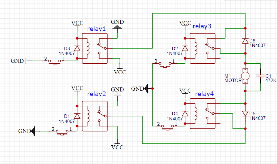
the purpose of relay 1 and 2 is to turn on and off the motor and relay 3 and 4 is the upper limit and lower limit of the sensor the push button are actually sensor.
when push button on relay 1 pressed, the motor will on and until push button on relay 3 is pressed only then the motor stop.
if push button on relay 2 is pressed, the motor will be in reverse until pushbutton on relay 4 is pressed, then the motor stop.
I am having some trouble with my schematic as the relay acting like having short when I connect the motor but once I disconnect the motor, it behave as expected, can I know where I done it wrong.
That dosn't make much sense, the bit " but once I disconnect the motor, it behave as expected," if you remove the motor the expectation is that the motor will not run at all.
If you remove the motor an replace it with a short circuit then yes you will short out the power supply.
Your schematic has not got any labels on the relay switch contacts and I am making the big assumption that they are being drawn in the normally closed position (Nc). Is it possible in your wiring you have mixed up the Nc with the normally open (No)?
im using this diagram and make adjustment based on this one for me to control the motor to run it forward or reverse depending on which button is pressed
Relays are not the best way to do this...
Motors will cause sparks and very high currents...
You miss a small capacitor over the motor.
And some diodes to take away the sparks.
A mosfet h-bridge module will be much better.
Do you have any idea of the stall current of your motor? Is it a hobby car motor ar a wheel chair motor...
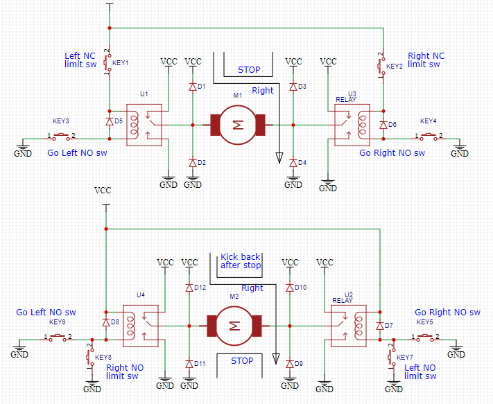
Limit switches are usually not done with a relay, but with two NC (roller) micro switches with diodes across. The right polarity of each diode stops the motor going in the wrong direction.
The right-hand side of this daigram shows how to wire the diodes.
Leo..
Im using a 472K ceramic capacitor with diode and Im using to drive my car power window. imma try it right now. please let me know if there are anything I missed
thank you
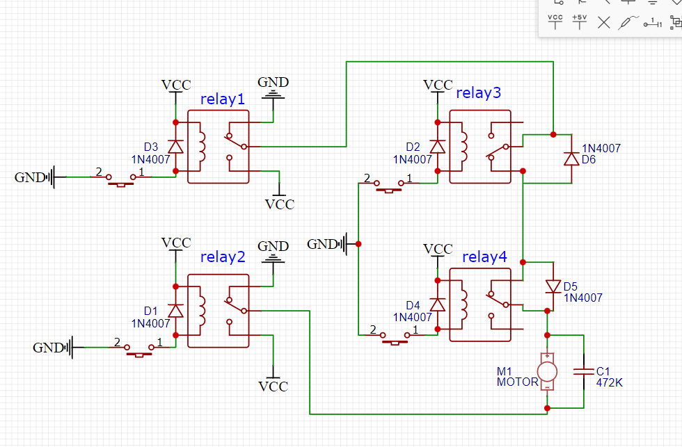
edit: I tried this diagram, with the diode but when relay 3 trigger, the motor do not stop. what I`m trying to do is either one of the relay 3 or 4 trigger, the motor stop. but so far if I disconnect the diode, the motor behave exactly as expected. how do I make the motor stop?
It sounds like you shorted the limit switches out, so they would not stop the motor.
The reason for the diodes is;
When you hit the limit the switch OPENS.
This cuts the current to the motor.
The diode is then in circuit, so when you reverse the current the diode conducts and the motor moves OFF the limit switch.
You have to have the diodes in the correct orientation for this to work.