[SOLVED] Relay won't switch in my project

Hi guys.

I'm currently working on a project that uses relay and water level sensor. The problem is, the relay won't switch and I was wondering whether its the program issue or hardware issue.

I'm unable to give you guys the picture, but the wiring is like this:
Relay 2 channel
DC + -> VCC of 5V Power Supply
DC - -> GND of 5V Power Supply
IN1 -> D3 NodeMCU
IN2 -> D4 NodeMCU

When I first power it up, the relay definitely switch, but when reaching the logic of the program, the relay stay silent.

What I want to achive is, when the program starts working R1 is on, but when the wLevel reach 2cm, R1 OFF and R2 On activating the water pump till the water is empty, then R1 is on again.

This is the whole code

#include <Wire.h>
#include <Blynk.h>
#include <LiquidCrystal_I2C.h>
#define BLYNK_PRINT Serial
#include <ESP8266WiFi.h>
#include <BlynkSimpleEsp8266.h>

//Initialize the LCD display
LiquidCrystal_I2C lcd(0x27, 16, 2);
char auth[] = "xxx";//Enter your Auth token
char ssid[] = "xxx";//Enter your WIFI name
char pass[] = "xxx";//Enter your WIFI password
BlynkTimer timer;

#define pinSensor A0  // mendefinisikan pin A0 sebagai pin yang berhubungan dengan sensor
#define PIN_RELAY_1  D3 // the Arduino pin, which connects to the IN1 pin of relay module
#define PIN_RELAY_2  D4 // the Arduino pin, which connects to the IN1 pin of relay module
int sensorValue = 0; // variable untuk menampung nilai baca dari sensor dalam bentuk integer
float tinggiAir = 0; // variabel untuk menampung ketinggian air
float sensorVoltage = 0; // untuk menampung nilai ketinggian air
int nilaiMax = 686; // nilai "sensorValue" saat sensor terendam penuh kedalam air, bisa dirubah sesuai sensor dan jenis air yang anda pakai
float panjangSensor = 4.0 ; // 4.0 cm

void setup() {
  Serial.begin(115200); 
  lcd.begin(); 
  lcd.backlight();
  pinMode(PIN_RELAY_1, OUTPUT);
  pinMode(PIN_RELAY_2, OUTPUT);
  digitalWrite(PIN_RELAY_1, HIGH);
  digitalWrite(PIN_RELAY_2, HIGH);
  Blynk.begin(auth, ssid, pass, "blynk.cloud", 80);
  lcd.setCursor(0, 0);
  lcd.print("Water level");
  lcd.setCursor(4, 1);
  lcd.print("Monitoring");
  delay(4000);
  lcd.clear();
  timer.setInterval(100L, wLevel);
}
void wLevel() {
   sensorValue = analogRead(pinSensor); // membaca tengan dari sensor dalam bentuk integer
  tinggiAir = sensorValue*panjangSensor/nilaiMax;
  sensorVoltage = sensorValue*5.0/686;
//sm
  Serial.print("Sensor Value = ");
  Serial.println(sensorValue);
  Serial.print("Sensor Voltage = ");
  Serial.println(sensorVoltage);
  Serial.print("Tinggi Air = ");
  Serial.println(tinggiAir);
  Serial.println();
  
  // Display ke LCD
  lcd.setCursor(0,0);
  lcd.print("WLevel:");
  lcd.print(tinggiAir);
  lcd.setCursor(12,0);
  lcd.print("cm");
  delay(1000);
  Blynk.virtualWrite(V0, tinggiAir);
  Blynk.run();
  if (tinggiAir >= 2) // if wlevel more than 2 cm, then
     {
        digitalWrite(PIN_RELAY_1, HIGH);
        digitalWrite(PIN_RELAY_2, LOW);
        lcd.setCursor(0,1);
        lcd.print("F:OFF P:ON");
        Blynk.logEvent("wlevel","wLevel more than 2cm"); 
        delay(7000);       
     }
  else
     {
       digitalWrite(PIN_RELAY_1, LOW);
       digitalWrite(PIN_RELAY_2, HIGH);
        lcd.setCursor(0,1);
        lcd.print("F:ON P:OFF");
        delay(2000);
     }
}
void loop() {
      Blynk.run();
     timer.run();
}
your delays() prevent the run() functions of the loop to run... blocking code for 7 seconds is a loooooong time

try rewriting this without blocking

For extra information and examples look at

1 Like

Hi, @jeonsann

Have you written some code to JUST test your relay?
If not then it might be a good idea to make sure it is not a hardware problem.

Can you please post a copy of your circuit, a picture of a hand drawn circuit in jpg, png?
Hand drawn and photographed is perfectly acceptable.
Please include ALL hardware, power supplies, component names and pin labels.

Thanks... Tom... :grinning: :+1: :coffee: :australia:

1 Like

Sorry, i will post the picture soon. But, yeah I just tried to use the code from two channel relays custom timing, and the switch is there.

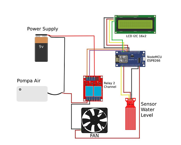
This is the wiring diagram:

1 Like

So, using delay is not going to make it happen?

Yes, delay() is very often hindering as it does not allow the controller to read sensors as quickly as required.

In your case you have defined a function wLevel that should be called every 100 msec while inside the function you use delays of 2000 and 7000 msec.

You don't need delays if you take a slightly different approach.

No guarantee that this works immediately in your environment here a version on Wokwi that should do it:

https://wokwi.com/projects/379549071654633473

I added two thresholds

  • startThreshold = 2;
  • stopThreshold = 1;

to get hysteresis for the pump switching.

Sketch
/*
   Forum: https://forum.arduino.cc/t/relay-wont-switch-in-my-project/1182004/4
   Wokwi: https://wokwi.com/projects/379549071654633473

*/
// For use outside of Wokwi
// comment the next line out for use or change it to #undef WOKWI
#define WOKWI

#ifdef WOKWI
#define BLYNK_TEMPLATE_ID "xxxxxxx"
#define BLYNK_TEMPLATE_NAME "xxxxxxx"
#define BLYNK_AUTH_TOKEN "xxxxxxxx"
#endif

#include <Wire.h>
#include <Blynk.h>
#include <LiquidCrystal_I2C.h>

#ifndef WOKWI
#define BLYNK_PRINT Serial
#include <ESP8266WiFi.h>
#include <BlynkSimpleEsp8266.h>
#endif

//Initialize the LCD display
LiquidCrystal_I2C lcd(0x27, 16, 2);
char auth[] = "xxx";//Enter your Auth token
char ssid[] = "xxx";//Enter your WIFI name
char pass[] = "xxx";//Enter your WIFI password
BlynkTimer timer;

#ifdef WOKWI
#define pinSensor   15  // mendefinisikan pin A0 sebagai pin yang berhubungan dengan sensor
#define PIN_RELAY_1  5 // the Arduino pin, which connects to the IN1 pin of relay module
#define PIN_RELAY_2  4 // the Arduino pin, which connects to the IN1 pin of relay module
#else
#define pinSensor A0  // mendefinisikan pin A0 sebagai pin yang berhubungan dengan sensor
#define PIN_RELAY_1  D3 // the Arduino pin, which connects to the IN1 pin of relay module
#define PIN_RELAY_2  D4 // the Arduino pin, which connects to the IN1 pin of relay module
#endif

constexpr int startThreshold = 2; // pumping shall start at startThreshold [cm] and above
constexpr int stopThreshold  = 1; // pumping shall start at stopThreshold  [cm] and below

int sensorValue = 0; // variable untuk menampung nilai baca dari sensor dalam bentuk integer
float tinggiAir = 0; // variabel untuk menampung ketinggian air
float sensorVoltage = 0; // untuk menampung nilai ketinggian air
int nilaiMax = 686; // nilai "sensorValue" saat sensor terendam penuh kedalam air, bisa dirubah sesuai sensor dan jenis air yang anda pakai
float panjangSensor = 4.0 ; // 4.0 cm


enum StatusType {CHECKLEVEL, LEVELHIGH, PUMPING};

StatusType status = LEVELHIGH;   // Let's start with LEVELHIGH to check level and set the display correctly

void setup() {
  Serial.begin(115200);
#ifdef WOKWI
  lcd.init();
#else
  lcd.begin();
  Blynk.begin(auth, ssid, pass, "blynk.cloud", 80);
#endif
  lcd.backlight();
  pinMode(PIN_RELAY_1, OUTPUT);
  pinMode(PIN_RELAY_2, OUTPUT);
  digitalWrite(PIN_RELAY_1, HIGH);
  digitalWrite(PIN_RELAY_2, HIGH);
  lcd.setCursor(0, 0);
  lcd.print("Water level");
  lcd.setCursor(4, 1);
  lcd.print("Monitoring");
  delay(4000);
  lcd.clear();
  timer.setInterval(100L, wLevel);
}


void wLevel() {
  sensorValue = analogRead(pinSensor); // membaca tengan dari sensor dalam bentuk integer
  tinggiAir = sensorValue * panjangSensor / nilaiMax;
  sensorVoltage = sensorValue * 5.0 / 686;
}

void loop() {
#ifndef WOKWI
  Blynk.run();
#endif
  timer.run();
  handleStatus();
}

void handleStatus() {
  switch (status) {
    case CHECKLEVEL:
      // Wait for level above threshold
      if (tinggiAir >= startThreshold) { // if wlevel more than startThreshold [cm], then
        status = LEVELHIGH;
        Serial.println("LEVELHIGH");
      }
      break;
    case LEVELHIGH:
      levelIsHigh();
      break;
    case PUMPING:
      if (tinggiAir < stopThreshold) { // if wlevel less than stopThreshold [cm] (use hysteresis!) then
        levelIsLowAgain();
        status = CHECKLEVEL;
        Serial.println("CHECKLEVEL");
      }
      break;
  }
  displayValues();
}

void displayValues() {
  static int oldSensorValue = -1; // variable untuk menampung nilai baca dari sensor dalam bentuk integer
  float oldTinggiAir = -1; // variabel untuk menampung ketinggian air
  float oldSensorVoltage = -1; // untuk menampung nilai ketinggian air

  if (oldSensorValue != sensorValue ||
      oldTinggiAir   != tinggiAir   ||
      oldSensorVoltage != sensorVoltage) {
    Serial.print("Sensor Value = ");
    Serial.println(sensorValue);
    Serial.print("Sensor Voltage = ");
    Serial.println(sensorVoltage);
    Serial.print("Tinggi Air = ");
    Serial.println(tinggiAir);
    Serial.println();
    // Display ke LCD
    lcd.setCursor(0, 0);
    lcd.print("WLevel:");
    lcd.print(tinggiAir);
    lcd.setCursor(12, 0);
    lcd.print("cm");
    oldSensorValue = sensorValue;
    oldTinggiAir   = tinggiAir;
    oldSensorVoltage = sensorVoltage;
#ifndef WOKWI
    Blynk.virtualWrite(V0, tinggiAir);
#endif
  }
}

void levelIsHigh() {
  digitalWrite(PIN_RELAY_1, HIGH);
  digitalWrite(PIN_RELAY_2, LOW);
  lcd.setCursor(0, 1);
  lcd.print("F:OFF P:ON");
#ifndef WOKWI
  Blynk.logEvent("wlevel", "wLevel more than 2cm");
#endif
  status = PUMPING;
  Serial.println("PUMPING");
}

void levelIsLowAgain() {
  digitalWrite(PIN_RELAY_1, LOW);
  digitalWrite(PIN_RELAY_2, HIGH);
  lcd.setCursor(0, 1);
  lcd.print("F:ON P:OFF");
  status = CHECKLEVEL;
  Serial.println("CHECKLEVEL");
}

Good luck!

1 Like

Hi there and welcome back!

Good diagram you produced, and being cooperative show us that you're serious about the matter. By the way, what software / website did you use to make the diagram?

Hi there. Thanks for your extra effort to help me. I will definitely try this when I'm available tomorrow.

Hi ledsyn, iirc I'm using Fritzing.

Hi, @jeonsann

Can you please post a copy of your circuit, a picture of a hand drawn circuit in jpg, png?
Hand drawn and photographed is perfectly acceptable.
Please include ALL hardware, power supplies, component names and pin labels.

Please show what your real power supply is.

Can you please post some pictures of your project.
So we can see your component layout.
The wiring of the relay does not look as thought it would do what you need.

Thanks... Tom... :grinning: :+1: :coffee: :australia:

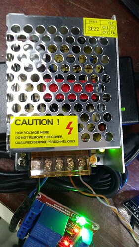
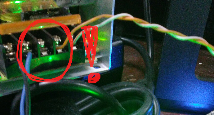
Hi, Tom. This is the picture of my components.

Thanks.. Now reverse engineer it.
And please post a copy of your circuit, a picture of a hand drawn circuit in jpg, png?
Hand drawn and photographed is perfectly acceptable.
Please include ALL hardware, power supplies, component names and pin labels.

Can you please post a link to data/specs of the relay module?
It has some jumpers.

Thanks... Tom.. :grinning: :+1: :coffee: :australia:


Hi,
Have you got a gnd connection between the MCU and the relay module?
Please include ALL connections/wires and pin names.

Tom.. :grinning: :+1: :coffee: :australia:

Where's Earth?

Hi Tom. I changed the relay with the black one, and the switching problem is solved. But there's another problem, the relay will only active when i connected VCC and GND of relay to VCC and GND of NodeMCU. I tried to use the vcc and gnd of power supply to power my LCD but, it just showing blank black bar.

Hi, @jeonsann

What black relay?

Tom.. :grinning: :+1: :coffee::australia:

This topic was automatically closed 180 days after the last reply. New replies are no longer allowed.