EDIT-1: The solution to the problem is (partly) given in my next post (#7).
EDIT-2: A pin / wiring layout of this (small) project is given in post #13 and #14.
Hello all,
I am encountering strange behavior when connecting a TowerPro MG995 to my Arduino UNO. I've tried many setups, e. g., connecting it directly to the Arduino or using a potentiometer to control the final position of the servo---always with the same behavior: The servo roughly drives to the commanded position but than moves back randomly. Using a for-loop to let the servo occupy all possible angles (0-179°), was weird too: At first, the motions were comparable to the first test case (moving back and forward) but after some seconds the servo stopped moving at all (just a humming noise when a new position was send by the Arduino). Note that I am using the (default) "Servo"-Arduino library.
I've uploaded a video demonstrating this behavor (using the "poti-setup"). You can download it here. The code for this setup is as follows (taken from here):
#include <Servo.h>
Servo myservo;
int potpin = 0;
int val;
void setup()
{
myservo.attach(9);
}
void loop()
{
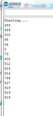
val = analogRead(potpin);
val = map(val, 0, 1023, 0, 179);
myservo.write(val);
delay(15);
}
Additionally, I've tried the following:
- Used an external power plug: The servo appeared to be more reactive but the overall "strange" behavior was the same.
- Connected another servo (TowerPro SG90): This servo worked well. Using the "poti-setup", I was able to set the position of the servo using the poti (as expected).
Does anyone have any idea what the problem is? I am assuming that the servo devices (BTW: both servos I am owning have this problem, except for the SG90) are simply broken ...? Any hints / suggestions are highly appreciated!
Thanks in advance!
Best regards,
CodeFinder
PS: I have another video showing the (working) result of connecting the SG90. If you need it, I can upload it as well. If you need more information, just ask me.