I'm having my first try at multiple displays, and it isn't going great. I'm sure this is something I'm doing wrong, obviously, but I can't figure it out.
I have a mix of little .96 128x64 OLEDs, with a mix of interfaces:
- 2x I2C
- 2x SPI with 7 pins (one white display, one yellow/blue, if that matters)
- 1x SPI with 6 pins (no reset)
I'd like to use (any) two for this project.
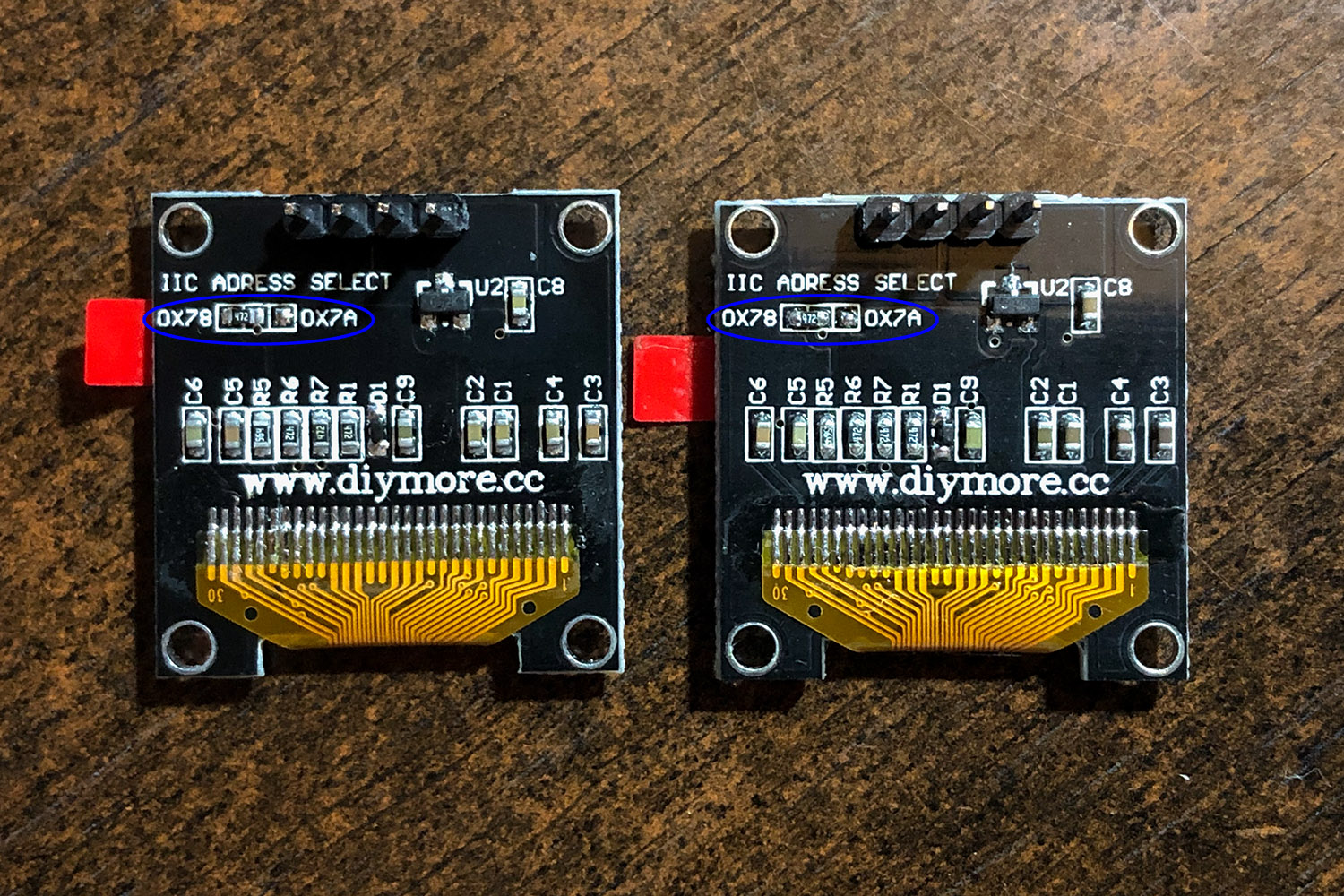
Unfortunately as far as I understand I can't use both I2C displays without re-soldering a tiny SMD on the back. Correct me if that's wrong.
Before I risk that I figure I could try the SPI. To at least get things to work I am sticking with only the two SPI with 7 pins. Even though the colors in the display are different, I assume they both function the same connection-wise and code-wise?
Regarding multiple SPI devices, I have read two slightly contradictory things:
- SPI devices can share all of the pins except each device must have its own CS pin.
...or...
- Each device must have its own CS AND Reset pin.
I've tried both of those options.
As you can see in the photo, the CLK (D0), MOSI (D1), and DC pins from the left go to the corresponding pins on the right, then over to the Redboard.
The CS always go to separate pins on the Redboard. In this photo the RST pins also go straight from each display to the Redboard. (But, again, I also tried with both Reset pins going to the same pin on the Redboard.)
Here is my code:
#include <SPI.h>
#include <Wire.h>
#include <Adafruit_GFX.h>
#include <Adafruit_SSD1306.h>

#define SCREEN_WIDTH 128 // OLED display width, in pixels
#define SCREEN_HEIGHT 64 // OLED display height, in pixels

// Declaration for SSD1306 display connected using software SPI (default case):
#define OLED_MOSI   9
#define OLED_CLK   10
#define OLED_DC    11

#define OLED_CS_left    7
#define OLED_RESET_left 8

#define OLED_CS_right   12
#define OLED_RESET_right 13

Adafruit_SSD1306 display_left(SCREEN_WIDTH, SCREEN_HEIGHT, OLED_MOSI, OLED_CLK, OLED_DC, OLED_RESET_left, OLED_CS_left);
Adafruit_SSD1306 display_right(SCREEN_WIDTH, SCREEN_HEIGHT, OLED_MOSI, OLED_CLK, OLED_DC, OLED_RESET_right, OLED_CS_right);

void setup() {
  Serial.begin(9600);

  // SSD1306_SWITCHCAPVCC = generate display voltage from 3.3V internally
  if (!display_left.begin(SSD1306_SWITCHCAPVCC)) {
    Serial.println(F("SSD1306 allocation failed: left"));
    for (;;); // Don't proceed, loop forever
  }

  display_left.clearDisplay();
  display_left.setTextColor(WHITE);
  display_left.setCursor(30,20);
  display_left.setTextSize(2);
  display_left.print("LEFT");
  display_left.display();

  // SSD1306_SWITCHCAPVCC = generate display voltage from 3.3V internally
  if (!display_right.begin(SSD1306_SWITCHCAPVCC)) {
    Serial.println(F("SSD1306 allocation failed: right"));
    for (;;); // Don't proceed, loop forever
  }

  display_right.clearDisplay();
  display_right.setTextColor(WHITE);
  display_right.setCursor(30,20);
  display_right.setTextSize(2);
  display_right.print("RIGHT");
  display_right.display();

  delay(10000);
}

void loop() {
}
No matter what I try, I can only get the left display to work. The Serial monitor just says "SSD1306 allocation failed: right".
I can switch the actual displays, and still only the left one works, so it's not a faulty display.
I assume I'm missing something obvious, and I apologize about my lack of knowledge regarding this.
Also, I assume I could mix one SPI and one I2C, but I feel like I should learn how this works anyhow, before going with a workaround like that.
Thanks for your help.