Edit: not sure why...but it works now.
Hello,
I'm having trouble using GPIO3 and GPIO1 (uart tx and rx pins) on an ESP8266 for basic discrete input & output when I'm already using other pins for SPI. On an ESP8266 (nodeMCU), I have the following:
- SPI OLED display (4 pins, SPI)
- Color sensor (5 pins, Discrete)
- single LED (1 pin discrete)
- single push button (1 pin discrete)
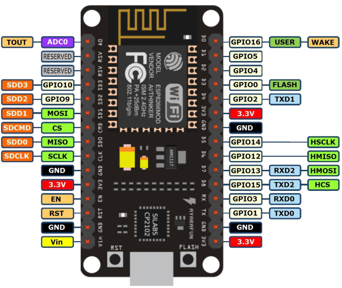
This diagram below lays out my pin mapping. The program works fine when I only have the OLED display and the color sensor going. As soon as I try to declare another pin as INPUT or OUTPUT for use as push button or LED, the SPI seems to stop working (the OLED display becomes blank after download).
I've run into these types of issues before probably because the ESP8266 is multiplexing some pins, but I didn't think RX and TX (GPIO3 & GPIO1) serial pins would be effected by SPI, since I'm pretty sure I've used SPI devices and enable serial uart for debug before.
Some things I've tried: moving the LED and push button to GPIO0 and GPIO15. Same effect, and I'm sure GPIO15 effects SPI. The OLED library I'm using for some reason makes me use GPIO4 and GPIO5 for the MISO and SS, instead of the regular HSCLK(GPIO14) and HMISO(GPIO12).
#include <SPI.h>
#include <SSD_13XX.h>

//SPI pins for OLED
#define __CS  4  //GPIO4 (D2) cable select (SS)
#define __DC  5   //GPIO5 (D1) MISO

//color sensor pins
#define S0 9    //GPIO9
#define S1 10    //GPIO10
#define S2 2    //GPIO2, D4
#define S3 12    //GPIO12, D6
#define sensorOut 16    //GPIO16, D0

int frequency = 0;
int R_value = 0;
int G_value = 0;
int B_value = 0;

//Using uart rx and tx pins for push button and LED instead of serial debug
#define pin_PB 3            //GPIO3 = RX pin
#define pin_otherLED 1  //GPIO1 = TX pin

SSD_13XX tft = SSD_13XX(__CS, __DC);

void setup() {
  //Serial.begin(115200);   //I'm not using uart, using these pins for push button and LED instead
  tft.begin();

  //color sensor pin configuration
  pinMode(S0, OUTPUT);
  pinMode(S1, OUTPUT);
  pinMode(S2, OUTPUT);
  pinMode(S3, OUTPUT);
  pinMode(sensorOut, INPUT);

  // color sensor Setting frequency-scaling to 20%
  digitalWrite(S0,HIGH);
  digitalWrite(S1,LOW);

  //!! --- Problem ---:  when ever I try to set input or output for LED or pushbutton,
  //  the SPI seems to stop working.  The OLED display stops working.

  pinMode(pin_PB, INPUT_PULLUP);    // breaks SPI OLED
  pinMode(pin_otherLED, OUTPUT);    // breaks SPI OLED

}


void loop(void) {

  //Read red
  digitalWrite(S2,LOW);
  digitalWrite(S3,LOW);
  frequency = pulseIn(sensorOut, LOW);
  R_value = frequency;
  //display red value
  tft.clearScreen();
  tft.setCursor(10, 0);
  tft.setTextColor(RED);
  tft.setTextScale(2);
  tft.println(R_value);
  delay(50);


  //Read green
  digitalWrite(S2,HIGH);
  digitalWrite(S3,HIGH);
  frequency = pulseIn(sensorOut, LOW);
  G_value = frequency;
  //display green
  tft.setCursor(10, 20);
  tft.setTextColor(GREEN);
  tft.setTextScale(2);
  tft.println(G_value);
  delay(50);


  //Read blue
  digitalWrite(S2,LOW);
  digitalWrite(S3,HIGH);
  // Reading the output frequency
  frequency = pulseIn(sensorOut, LOW);
  B_value = frequency;
  //display Blue
  tft.setCursor(10, 40);
  tft.setTextColor(BLUE);
  tft.setTextScale(2);
  tft.println(B_value);


  delay(1000);

}