Hello,
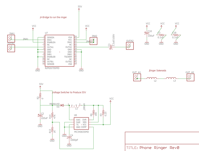
I've got an antique phone that I want to wire up as a doorbell via Arduino. I've got a boost converter to kick supply up to 40V or so, then an H-bridge to flip the voltage as controlled by Arduino input. The phone has two solenoids connected in series, with about 30ohm resistance, haven't measured the inductance yet.
I copied this circuit from the sparkfun product here:
My questions:
- In this configuration, I can't use a flyback diode because the voltage flips direction, right?
- If I'm using 5V supply instead of 3.8V, do I need to adjust the values of R3/C4? I'm having some trouble understanding the data sheet.
- Any other comments?
Thanks for the help, I have an understanding of how inductance works but haven't worked with boost converters/solenoids before.

