Hello everyone,
Can you help me with my code. I have attached it below
I am using the Nick Gammon example code and have also included some print statements for debugging.
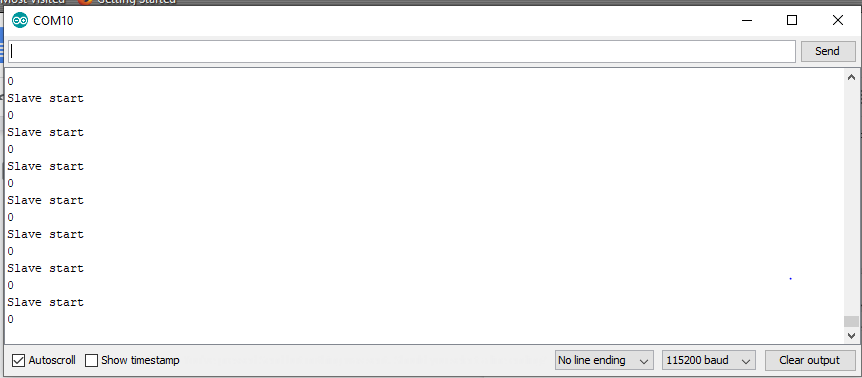
The output of both master and slave has been attached. It is printing garbage value.
Master code
#include <SPI.h>

void setup (void) {
   Serial.begin(115200); //set baud rate to 115200
   digitalWrite(SS, HIGH); // disable Slave Select
   SPI.begin ();
   SPI.setClockDivider(SPI_CLOCK_DIV8);//divide the clock by 8
}

void loop (void) {
   char c;
   digitalWrite(SS, LOW); // enable Slave Select
   Serial.println(" SS is enabled now");
   // send test string
   for (const char * p = "Hello, world!\r" ; c = *p; p++) {
      SPI.transfer (c);
      Serial.print(c);
   }
   Serial.println(" Data should have been sent");
   digitalWrite(SS, HIGH); // disable Slave Select
   delay(2000);
}
Slave Code
#include <SPI.h>
char buff [50];
volatile byte indx;
volatile boolean process;

void setup (void) {
   Serial.begin (115200);
   pinMode(MISO, OUTPUT); // have to send on master in so it set as output
   SPCR |= _BV(SPE); // turn on SPI in slave mode
   indx = 0; // buffer empty
   process = false;
   SPI.attachInterrupt(); // turn on interrupt
}
ISR (SPI_STC_vect) // SPI interrupt routine {
{
  byte c = SPDR; // read byte from SPI Data Register
   if (indx < sizeof buff) {
      buff [indx++] = c; // save data in the next index in the array buff
      if (c == '\r') //check for the end of the word
      process = true;
   }
}

void loop (void) {
  Serial.println("Slave start");
  Serial.println(process);
   if (process) {
      process = false; //reset the process
      Serial.println (buff); //print the array on serial monitor
      indx= 0; //reset button to zero
   }
}
-Thanks in Advance for your help and time!