I've been trying to learn SPI, using an EEPROM 25L4005. I've tinkered it all day, read the datasheet multiple times, but still the output from the eeprom is FF. The data is sent to the slave correctly, but MISO doesn't seem to respond. I taught there was something wrong with the IC so ran an simulation on proteus software, but still the problem persists( tried debugging using SPI debugger in the simulator ). I don't have an logic analyzer to test practically. There is a similar EEPROM named 25LC512, using this in the simulator works perfectly without any errors. Communication is clean. what can be the possible problem here
#include <SPI.h>
#define READ 0x03
#define WRITE 0x02
#define WREN 0x06  // write enable

const int csPin = 10;
const int wpPin = 9; // For this sketch you could also leave the wpPin unconnected
const int writeCycle = 5;

void setup(){
  pinMode(csPin, OUTPUT);
  digitalWrite(csPin, HIGH);
  pinMode(wpPin, OUTPUT);
  digitalWrite(wpPin,HIGH);
  SPI.begin();
  Serial.begin(9600);

  int intToWrite = 42;
  eepromWriteInt(4, intToWrite);
  intToWrite = -1111;
  eepromWriteInt(6, intToWrite);

  int intToRead = 0;
  intToRead = eepromReadInt(4);
  Serial.print("intToRead (Address = 4): ");
  Serial.println(intToRead);
  intToRead = 0;
  intToRead = eepromReadInt(6);
  Serial.print("intToRead (Address = 6): ");
  Serial.println(intToRead);
}

void loop(){}

void eepromWriteEnable(){
  digitalWrite(csPin, LOW);
  SPI.transfer(WREN);
  digitalWrite(csPin, HIGH);
}

void eepromWriteInt(int addr, int value){
  eepromWriteEnable();
  // If you want to change the SPI clock speed, uncomment the following line and adjust
  SPI.beginTransaction(SPISettings(4000000, MSBFIRST, SPI_MODE0));
  digitalWrite(csPin, LOW);
  SPI.transfer(WRITE);
  SPI.transfer((byte)(addr>>8));
  SPI.transfer((byte)(addr&0xFF));
  SPI.transfer((byte)(value>>8));
  SPI.transfer((byte)(value&0xFF));
  digitalWrite(csPin, HIGH);
  SPI.endTransaction(); // Uncomment if you have uncommented SPI.beginTransaction()
  delay(writeCycle);
}

int eepromReadInt(int addr){
  byte MSB = 0;
  byte LSB = 0;
  int value = 0;
  SPI.beginTransaction(SPISettings(4000000, MSBFIRST, SPI_MODE0));
  digitalWrite(csPin, LOW);
  SPI.transfer(READ);
  SPI.transfer((byte)(addr>>8));
  SPI.transfer((byte)(addr&0xFF));
  MSB = SPI.transfer(0x00);
  LSB = SPI.transfer(0x00);
  digitalWrite(csPin, HIGH);
  SPI.endTransaction();
  value = (int)((MSB<<8)|LSB);
  return value;
}
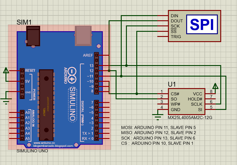
below is the arduino code, works for both IC's no need for changes, same command instructions and sequence.
datasheet of 25L4005 the one with the problem. And this is the datasheet for 25LC512 the working one.