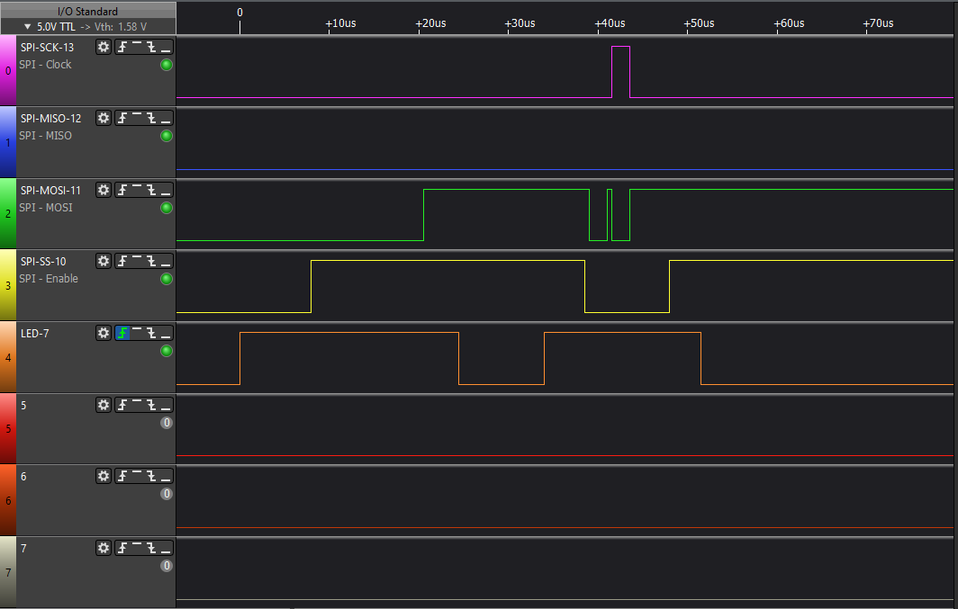
When run, the SPI does erratic outputs... Eg SCK only does 1 or 2 cycles, but MOSI does bit-changing, and SS is Low.
This problem is present whenever I choose a library example sketch, which includes code to talk on the SPI interface. Eg DigitalPotControl
While I can write code that works the SPI correctly, none of the supplied examples will work with the SPI interface.
They all have the same result as shown.
Please HELP !
Please see attached pics and code.
StartUp.png - has the 1.5 second delay and 3 pulses
T0_init.png - has the init function.
T1.png - is the first data message
T2.png - is the 2nd data message
Also,
Q1) why is there a 1.5 second delay when the CPU is coming out of RESET ? (on ALL code)
Q2) why is there 3 pulses on the SCK pin when released from RESET ?
Can the bootloader startup be avoided?
Yes the analyser will decode, but cannot make sense of this.
I will send trace of good spi I wrote from scratch tomorrow.
The question is what is going wrong?
You have also connected a ground wire on your logic analyser to the Arduino ? That could be one source of inexplicable results.
I'd but some delay statements in the code so there is a clear distinction between (a) the bootloader activity on SCK, (b) the initialisation of SPI and the enable pin, and (c) the individual cycles of connecting to the digital pot over SPI.
I have attached some tests on the SPI interface.
HelloWorld.ino_0 raw SPI commands – works Ok – see HW_SPI-0.png and HW-SPI-01.png
HelloWorld.ino_begin library SPI commands – FAILS ! – see HW_SPI-begin.png
HelloWorld.ino_begin_trans library SPI commands with BeginTransaction call – works Ok – see HW_SPI-begin_trans.png
It seems that the SPI can not operate when SPRn bits (in SPCR) are 00 or 01. Must be 10 or 11 to work !?
My cpu clock is 16MHz.
The speed value in SPISettings does Not change the baud rate…why not ?
What is the correct way to set the baud rate and modes etc for SPI ?
Ie how to set variables that are defined in the librarys.
( the only way I can see is to hack the library files…not a good idea as this affects ALL programs that use librarys. )
The problem is that you have configured your logic analyser with a data rate which is too low for the default SPI settings. This below while running your code is 25MHz. The SPI clock is 4MHz and your Logic Analyser appears to be set at 500KHz. What Logic Analyser are you using, incidentally.
Hi,
Can you please post your code in code tags and your schematic as a jpg?
Its not encouraged to sent files zipped up, some platforms have problems opening them for a start.
My approach was, I believe, perfectly reasonable.
You have presented a concrete failure case which I attempted to duplicate. I used my logic analyser but could not repeat your error so I looked further. Clear from you screen shots was that the sampling frequency was far too low at 500KHz for a signal clocked at 4MHz. So your testing method is flawed and I expect you correct your error and repeat the tests. This because it is difficult to have confidence in the rest of your findings, each of which you supported with logic analyser traces, and may, for the same reason, be equally flawed. Further, it would be unusual (but not impossible) to find a fundamental error in a mature library like SPI.
If you still believe there is a specific error in the SPI library then post a minimal-reproducible code sample together with a statement of expected and actual results.
PS
This problem first started when I tried to build a Mega2560 and CANbus shield, which has the same SPI problem. I was using IDE 1.8.x and was hoping updating to IDE v2.0 may fix things, but it didnt.
Sorry, you seem to have misunderstood, can you post a schematic of how you have connected the controller to the rest of your hardware, the power supply and your SPI connections.
Not the controller schematic itself.
PLEASE post your code.
To add code please click this link;