Square Wave Offset between XOscillo and other Arduino

Hello,

I've got a few problems analyzing a square wave that is fed into an Atmega328P-PU-based standalone circuit using the Atmega's interrupts and I would appreciate any help.

I'm currently still working on a standalone circuit which switches my car stereo into mute when reverse gear is detected... which is standard nowadays in many cars.

But because that would be far too simple and unexciting :wink: , my muting device circuit will also monitor the car's speed using the car's GALA speed signal to determine when to switch in and out of mute. The speed signal is basically a square wave with fixed peak/trough ratio. At low speed, the wave cycles in milliseconds become longer (or zero at standstill), and the faster the car moves, the shorter they get. The Atmega analyzes this wave using one of the interrupt pins.

So far so good, I've done enough tests with my car to know what the wave looks like, and which frequency cycle lengths occur at which vehicle speeds.

I've rigged up a simulation environment around my muting device circuit, where another Atmega328P-PU on a breadboard creates a square wave identical to that in my car by means of simple HIGH/LOW bit banging. This bit banging circuit also features an analog rotary potentiometer to manipulate the wave cycle length.

Additionally, a second Arduino Uno board is used to monitor the bit-banging wave by means of the XOscillo oscilloscope software.

The problem now is that what I see on my Xoscillo doesnt equal the wave cycle length which the Arduino on the muting device circuit gets. For my muting device to work as planned in my car, however, it is crucial that the wave cycles are measured/interpreted accurately.

This is the part of my code I've uploaded to the muting device which picks up the bit-banging square wave, and when the project is finished, the car's GALA signal (the entire code is over 400 lines and not important for us here):

// GALA signal cycle length calculation variables

volatile boolean countBegin = false;

volatile unsigned long CycleLength;
volatile unsigned long MillisAtFirstChange;
volatile unsigned long time;

int SquareWave = 2;


void setup(){

       Serial.begin(9600);

       attachInterrupt(digitalPinToInterrupt(SquareWave), DeactMute, RISING);

}


// GALA Signal ISR


void DeactMute(){

    if(!countBegin){
	
        time = millis();
        MillisAtFirstChange = time;
	countBegin = true;
	}

    else{
	
        time = millis();
        CycleLength = time - MillisAtFirstChange;
        countBegin = false;
        }


//Just for testing purposes, cycle length is printed out via serial:
	
	Serial.println(CycleLength);
    	
    }

So far, so good... but here's what happens when I compare the cycle length measured by my muting device circuit with what the XOscillo gives me:

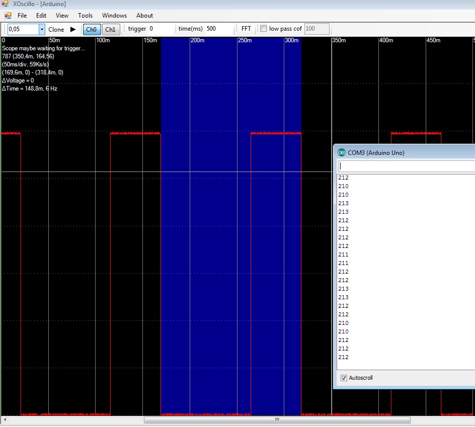
As you can see, the XOscillo gives out shorter cycle lengths than the muting device circuit. I've dialed the cycle length up and down using the bit banging circuit's potentiometer, and the difference seems to be a more or less constant factor of 1.4 between the muting device and the XOscillo.

Can somebody give me a few pointers how I can fix this?

  • carguy

At first glance I don't see anything that would stop your code from working.

Have you tried bit-banging a constant signal (say 100ms on/off) instead of something that varies with the pot? With a known constant signal you can tell whether your Arduino or the one using XOscillo is correct.

BigBobby:
At first glance I don't see anything that would stop your code from working.

Have you tried bit-banging a constant signal (say 100ms on/off) instead of something that varies with the pot? With a known constant signal you can tell whether your Arduino or the one using XOscillo is correct.

I just did that, and here's where it gets really weird... the Atmega on my muting device gives out the correct fixed cycle length that I just set the bit-banging chip's code to, whereas the XOscillo is once again off by a factor of 1.43.

I have just tried the Scorpino oscilloscope software, and it too actually gives me the correct values. So it's XOscillo that's somehow not working right.

Sadly, this also means I am going to have to go back to measuring my car's GALA signal at different speeds, because I just found out that the difference between the XOscillo's reading and the actual cycle length isn't constant when the cycle length gets shorter with increased speed (~15 mph and beyond). If it was a constant, then I could simply multiply the trigger thresholds in my code by the divergence factor...

carguy:
I just did that, and here's where it gets really weird... the Atmega on my muting device gives out the correct fixed cycle length that I just set the bit-banging chip's code to, whereas the XOscillo is once again off by a factor of 1.43.

I have just tried the Scorpino oscilloscope software, and it too actually gives me the correct values. So it's XOscillo that's somehow not working right.

Sadly, this also means I am going to have to go back to measuring my car's GALA signal at different speeds, because I just found out that the difference between the XOscillo's reading and the actual cycle length isn't constant when the cycle length gets shorter with increased speed (~15 mph and beyond). If it was a constant, then I could simply multiply the trigger thresholds in my code by the divergence factor...

I see. You actually would have preferred for the bug to be in your code instead of XOscillo :slight_smile:

A couple other things about your code:

  1. In these applications you typically see a hardware counter used instead of an interrupt. In your main loop you would then calculate pulses over a period of time to get speed (e.g. pulses/sec). The benefit of this is you can save potentially hundreds of interrupts firing every second.

  2. The pulses in your example seem to be pretty long, however. If they're always going to be large fractions of a second then using interrupts to measure period is fine (only dozens of interrupts firing every second). You don't need to only measure every other pulse, however. After the very first one, you can measure every subsequent pulse by changing one line of your code.

void DeactMute(){

    if(!countBegin){
	
        time = millis();
        MillisAtFirstChange = time;
	countBegin = true;
	}

    else{
	
        time = millis();
        CycleLength = time - MillisAtFirstChange;
        MillisAtFirstChange = time;
        }


//Just for testing purposes, cycle length is printed out via serial:
	
	Serial.println(CycleLength);
    	
    }

BigBobby:
I see. You actually would have preferred for the bug to be in your code instead of XOscillo :slight_smile:

Well yes... that's easier to fix, not having access to the source code of XOscillo, let alone knowing where to look for or find the bug within that application... :wink:

BigBobby:
A couple other things about your code:

  1. In these applications you typically see a hardware counter used instead of an interrupt. In your main loop you would then calculate pulses over a period of time to get speed (e.g. pulses/sec). The benefit of this is you can save potentially hundreds of interrupts firing every second.

You mean, it would be kind of an I2C architecture, with a separate chip just counting the pulses?

Interesting concept, but if you want to have it "all in one", interrupts are still the way to go, right (still kinda new to the concept of interrupts)?

Is it bad for the chip when it's constantly exposed to interrupt triggering? I've had this one chip on my test rig here for weeks and it's been running for many hours at a time just to see how my circuit would cope with real-life conditions...

BigBobby:
2. The pulses in your example seem to be pretty long, however. If they're always going to be large fractions of a second then using interrupts to measure period is fine (only dozens of interrupts firing every second).

I've done a few tests with the XOscillo hooked up right to my car's GALA signal; when you slow down, the pulse length gets longer and is infinite at standstill, and then gradually picks up as you accelerate. 12.5 mph (20 kph) is going to be one of my trigger speeds, at which pulse length is 50 ms... now adjusted for the XOscillo's "built-in" measuring error.

At that speed, if you're in forward gear, the mute will deactivate itself... the mute function is sustained for 30 seconds after you've gone back out of reverse gear, to eliminate "on" and "off"s while you're maneuvering in a parking space. And then when you go forward and pull out of a parking space within those 30 seconds, if you go faster than 12 mph, the mute will deactivate itself before that time. So 12.5 mph @ 50 ms is really what I am working with here.

BigBobby:
You don't need to only measure every other pulse, however. After the very first one, you can measure every subsequent pulse by changing one line of your code.

void DeactMute(){

if(!countBegin){

time = millis();
       MillisAtFirstChange = time;
countBegin = true;
}

else{

time = millis();
       CycleLength = time - MillisAtFirstChange;
       MillisAtFirstChange = time;
       }

//Just for testing purposes, cycle length is printed out via serial:

Serial.println(CycleLength);
   
   }

So you're saying, don't set CountBegin to false in the else{} bracket? Doesn't that mean that the Arduino will always count the intervals from the first time the interrupt was triggered?

  • carguy

carguy:
You mean, it would be kind of an I2C architecture, with a separate chip just counting the pulses?

No, you'd do it all with the Arduino. The PD4 and PD5 pins have a dual purpose as T0 and T1. There is hardware in the microprocessor to count pulses on these pins entirely in hardware. it looks like this thread discusses it -> T1 timer counter sketch - Programming Questions - Arduino Forum

carguy:
Is it bad for the chip when it's constantly exposed to interrupt triggering? I've had this one chip on my test rig here for weeks and it's been running for many hours at a time just to see how my circuit would cope with real-life conditions...

They're not going to hurt your Arduino, they're just nice to avoid if they're not necessary. Every time your ISR runs, some other piece of code takes longer to complete since it has to wait for your ISRs to finish. Also, when your ISR is running, other ISRs must be delayed. If your pulses/sec get high (like hundreds or thousands of times a second), it really starts to affect the operation of your other code. That said, there are times that's still the right thing to do...it's just good to avoid it if they're unnecessary.

carguy:
I've done a few tests with the XOscillo hooked up right to my car's GALA signal; when you slow down, the pulse length gets longer and is infinite at standstill, and then gradually picks up as you accelerate. 12.5 mph (20 kph) is going to be one of my trigger speeds, at which pulse length is 50 ms... now adjusted for the XOscillo's "built-in" measuring error.

At that speed, if you're in forward gear, the mute will deactivate itself... the mute function is sustained for 30 seconds after you've gone back out of reverse gear, to eliminate "on" and "off"s while you're maneuvering in a parking space. And then when you go forward and pull out of a parking space within those 30 seconds, if you go faster than 12 mph, the mute will deactivate itself before that time. So 12.5 mph @ 50 ms is really what I am working with here.

Given this data, it sounds like you're measuring the pulses the correct way. These signals are very slow.

carguy:
So you're saying, don't set CountBegin to false in the else{} bracket? Doesn't that mean that the Arduino will always count the intervals from the first time the interrupt was triggered?

Did you notice that I reset "MillisAtFirstChange" to "time" in the else block? That's what allows you to measure each pulse. For example, these are some sample values for a few pulses:

pulseNumber millis countBegin MillisAtFirstChange CycleLength
0 0 false 0 0
1 212 true 0 0
2 425 true 212 213
3 639 true 425 214

BigBobby:
No, you'd do it all with the Arduino. The PD4 and PD5 pins have a dual purpose as T0 and T1. There is hardware in the microprocessor to count pulses on these pins entirely in hardware. it looks like this thread discusses it -> T1 timer counter sketch - Programming Questions - Arduino Forum

Interesting... I'll look into that....

BigBobby:
They're not going to hurt your Arduino, they're just nice to avoid if they're not necessary. Every time your ISR runs, some other piece of code takes longer to complete since it has to wait for your ISRs to finish. Also, when your ISR is running, other ISRs must be delayed. If your pulses/sec get high (like hundreds or thousands of times a second), it really starts to affect the operation of your other code. That said, there are times that's still the right thing to do...it's just good to avoid it if they're unnecessary.

I had the car on a lift today with the wheels spinning free and scanned the signal again at different speeds... because my XOscillo readings were basically garbage and I want to get this right. The pulse lengths at which my muting device will actually do something (i.e. do something with a triggered "RISING" interrupt) are between 50 (12.5 mph) and 115 (6.5 mph) ms. Which means no more than 20 pulses per second. Pulse length goes down and towards zero at higher speeds (I had the car up to about 45 mph on the lift), but because the device isn't supposed to do anything at speeds like that and just waits for the next time you stop and put it in reverse, it won't matter if the interrupts interrupt the loop code 1000 times a second at 60 mph.

To briefly explain all the device's features:

  • switches the radio to mute in reverse gear (gets factory +12V reverse signal from fuse panel), by toggling a relay that switches GND through to the radio's designated mute pin.

  • stays in mute for 30 seconds after the car is out of reverse gear.

  • if forward movement of more than 12.5 mph (20 kph) is detected during those 30 seconds, mute is deactivated (i.e. when pulling out of a parking space back into traffic). This is done by using Interrupt pin 2.

  • if mute is activated and the car is in standstill (either in forward or reverse gear), mute can be deactivated by turning the rotary encoder that is the radio's volume knob. This is done by listening for "CHANGE" on interrupt pin 3.

  • if the car is in reverse, with mute deactivated after turning the volume knob, mute is reactivated again if the car is backing at more than 10 kph (6.25 mph).

I got the idea for this project after I had a little accident in a parking lot, with the stereo booming and not hearing the beep of my parking sensors, I backed into somebody who was right at that moment pulling around a curve. I had a rental car a few months ago, and it too had parking sensors, and all the above features that I am now trying to implement with my circuit. It's all already soldered together as a standalone circuit and almost ready to install, the only thing is that I'm having trouble with a few bugs, which are mainly that the code function interpreting the rotary encoder volume knob movement isn't reliably doing yet what I want it to do. Other than that, the project is actually 90% finished.

BigBobby:
Did you notice that I reset "MillisAtFirstChange" to "time" in the else block? That's what allows you to measure each pulse. For example, these are some sample values for a few pulses:

I get it now... you're right... that makes the code in that section a bit more elegant. Thanks! :wink:

  • carguy