I am almost done here with an Atmega328P-PU based standalone device that switches my car stereo to mute when I've got the transmission in reverse, so that I can hear the beeping of the parking sensors better (it also helps you concentrate when backing into a narrow inner-city parking space with little room for error ). Everything is working as it should. Everytime you put the car in reverse, the stereo goes mute, and stays mute for another ten seconds after you've put it out of reverse, so that the stereo doesn't come on again all the time while you are still maneuvering backwards and forwards.
But now, I've had the brilliant idea to add a feature to my circuit that deactivates the ten-second mute when you're pulling back into moving traffic, because I think it'll be annoying if you're pulling out of a parking space and you're already back in traffic, but the stereo is still in mute for another up to 10 seconds.
In my car (2000 Audi A4 sedan), there's a wire in the center console loom which supplies a speed signal to the stereo. My idea now is to figure out how the signal behaves at a speed of roughly 15 mph, so that I could feed that data into the Atmega, which will then cut out the mute if it detects a signal that corresponds to that speed of 15 mph.
Apparently, it's not a standard square signal, however, but one where the signal peak lengths stay constant and only the trough lengths vary (or was it the other way round? It is one of the two). I am not sure if that really makes the signal useable with the PulseIn() function of the Arduino.
Another idea would be to simply measure the voltage of the speed signal wire. Apparently, when the car is not moving, the wire's voltage is around 12.5 volts, and the voltage goes down the faster you go. So I figured that maybe I should just plug the signal wire into one of the Atmega's analog inputs, and read the voltage as an analog value.
I know that I am going to have to do something to step down the up-to 12.5V from the car's circuit; I'll probably just put in a voltage divider with 10K and 15K resistors and a Schottky diode.
Any thoughts on how the speed signal is best processed "code-wise" for what I have in mind here?
In my car (2000 Audi A4 sedan), there's a wire in the center console loom which supplies a speed signal to the stereo.
Why does your radio need to know how fast you are going? Does it turn the volume up the faster you go?
if it detects a signal that corresponds to that speed of 15 mph.
Or higher, presumably.
I am not sure if that really makes the signal useable with the PulseIn() function of the Arduino.
Nothing substitutes for experience. An alternative would be to feed the signal to an interrupt pin, with CHANGE as the trigger type. Record when the signal goes HIGH and when it goes LOW. The difference between the HIGH to LOW transition times will be constant, or not. The difference between the LOW to HIGH transition times will be constant, or not. The one that is not constant is the interesting one. You can then change the type from CHANGE to RISING or FALLING, depending on which turns out to be interesting.
PaulS:
Why does your radio need to know how fast you are going? Does it turn the volume up the faster you go?
Yes, it did that on most factory-supplied car stereo variants back in the day. Also, from the 1998 model year, the A4 could be ordered with built-in sat nav, which also needs the speed signal, because it calculates the car's position "redundantly", using both the speed signal and the GPS reading (quite practical in very long tunnels). I've retrofitted my car with a later-model Audi factory sat nav, and at first, it had trouble "locking on", because I actually forgot to connect the speed signal wire.
Most modern cars (since about 2003/2004, give or take) distribute the speed signal digitally via the car's CAN network as a continuous octet stream. And most factory sat nav's still calculate your position redundantly. The CAN signal is probably much trickier to read and process. Although there are CAN shields for the Arduino.
PaulS:
Nothing substitutes for experience. An alternative would be to feed the signal to an interrupt pin, with CHANGE as the trigger type. Record when the signal goes HIGH and when it goes LOW. The difference between the HIGH to LOW transition times will be constant, or not. The difference between the LOW to HIGH transition times will be constant, or not. The one that is not constant is the interesting one. You can then change the type from CHANGE to RISING or FALLING, depending on which turns out to be interesting.
Hm... I've still got an unused Atmega328P and a serial display lying around here... maybe I'll put together a circuit whose sole purpose is going to be processing the signal and displaying its values on the LCD display. And then to use my "findings" in my muting device.
Hm... I've still got an unused Atmega328P and a serial display lying around here... maybe I'll put together a circuit whose sole purpose is going to be processing the signal and displaying its values on the LCD display. And then to use my "findings" in my muting device.
Seems pretty exciting; this could potentially show me in great detail how the signal behaves with changing vehicle speed.
I'm going to have to get back to it this weekend, but that could save me quite a bit of work.
EDIT:
Here's a youtube vid where somebody hooked the odometer of an earlier Audi model up to an oscilloscope... this odometer is from an older car, but I am pretty sure the signal shape will not have changed fundamentally from one model generation to the next:
As you can see, the speed signal conveys speed information by varying the highs, by elongating or shortening them, while the signal lows pretty much stay the same regardless of the speed reading.
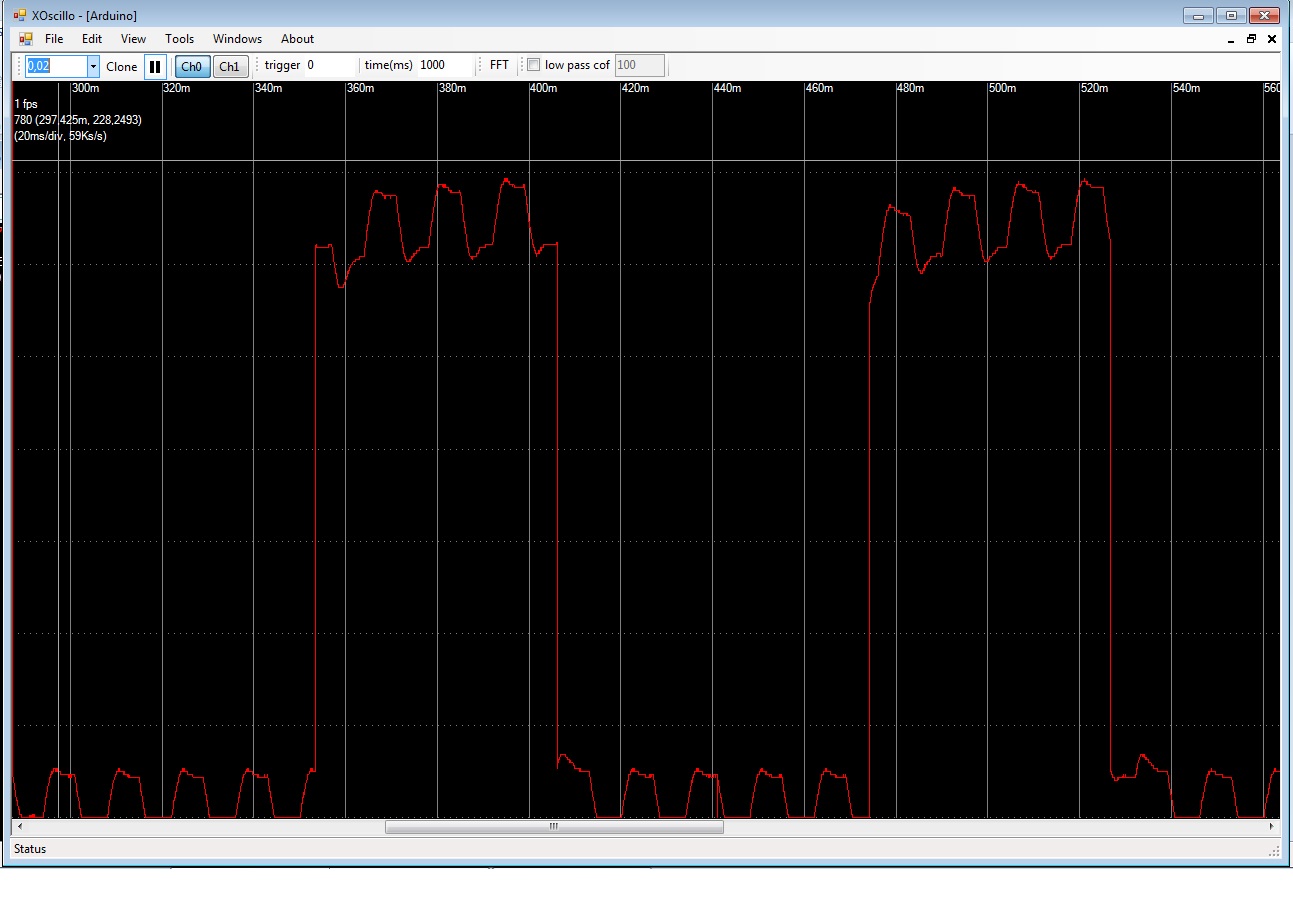
in the mean time, I've gone ahead and simulated a PWM with my one Arduino Uno board by means of simple bit-banging and thus switching an output pin high and low alternatingly.
Now when I take my other Arduino Uno and analyze the signal using XOscillo, I get a nice crisp PWM graph which should be easy to make use of with the Arduino's interrupts:
This is using a voltage divider made by simply arranging two fixed-value resistors in such a way that the output voltage is reduced to a certain lower voltage. Fundamentally, this is what I am going to have to do in my car to step down the 12V from the signal wire to a more Arduino-friendly 5V.
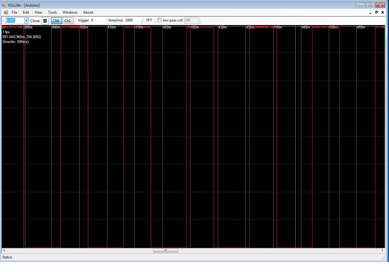
However, something needs to be done to protect the Arduino from voltage spikes in a car environment. So I added a 4V zener diode between the resistors and the input pin just to see how that would affect the signal curve... and this is what I got:
You see the problem... with a signal like that, I can neither detect a "rising" nor a "falling" or a "change" with any degree of accuracy with the Arduino's interrupts.
Should I just equip my voltage divider with bigger resistors, which will maybe step down the voltage to 2 or 3 volts, which will still be enough for the Arduino to tell "risings" from "fallings" while protecting the circuit from voltage spikes?