What do you mean by "pull the pin on the slave side"? Usually the master has full control over the SS pin, and the slave merely listens to know when it is being accessed.
The SS pin on the slave is supposed to be brought low to tell it that it's being talked to, and otherwise kept high. On the master, I think the SS pin needs to be kept as an OUTPUT or high.
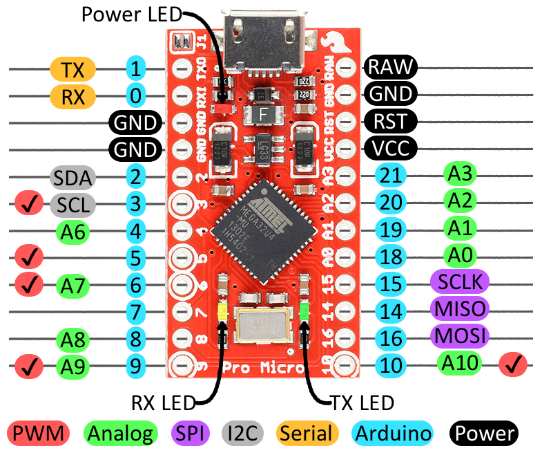
On the micro, this pin is PB0... which appears to be used for the RX light, and isn't broken out.
Mangle or remove the LED, solder (and glue in place, else it'll fatigue and break) a wire to the end that goes to the chip, and there's your connection point.
KeithRB:
What do you mean by "pull the pin on the slave side"? Usually the master has full control over the SS pin, and the slave merely listens to know when it is being accessed.
Yes, I know I have to configure it as o/p high on master and I/p high on slave.
But I couldn't find it on pro micro board.
DrAzzy:
The SS pin on the slave is supposed to be brought low to tell it that it's being talked to, and otherwise kept high. On the master, I think the SS pin needs to be kept as an OUTPUT or high.
On the micro, this pin is PB0... which appears to be used for the RX light, and isn't broken out.
Mangle or remove the LED, solder (and glue in place, else it'll fatigue and break) a wire to the end that goes to the chip, and there's your connection point.
It's digital pin 17 from within code.
No, I don't want to do this modification.
OK, I want to understand if they didn't include the SS pin on the I/O pins, then how the pro micro suppose to work? would it work with only 3 pins? MOSI MISO SCK.
Works as a master no prob (you can easily use a different pin on the master to drive the slave's SS pin), but maybe not as a slave... I'm not that familiar with slave SPI operation, not sure if you need to use the SS pin for slave.
And yeah, I realized that mod wouldn't work without you defanging the use of that port in response to serial use, meaning hacking around in the core...
KeithRB: Any pin can be SS, that is under your control. That way you can talk to multiple SPI devices.
I know it could be any pin on the master side, but has to be specific one on the slave side which is not specified on the pinout of the pro micro board.
But I think since they didn't include in in the I/O of the pro micro then it's not important.
I tried different boards but didn't work I think the problem in my code.
Which I have to include now in this thread or another one.
DrAzzy:
not sure if you need to use the SS pin for slave.
That's what I want to figure out, but since they didn't include it on pro micro pinout then it's not important.
Because I changed the boards and configured the SS pin and pulled it low and the code didn't work. The TX function is not compiling and executing the next line.
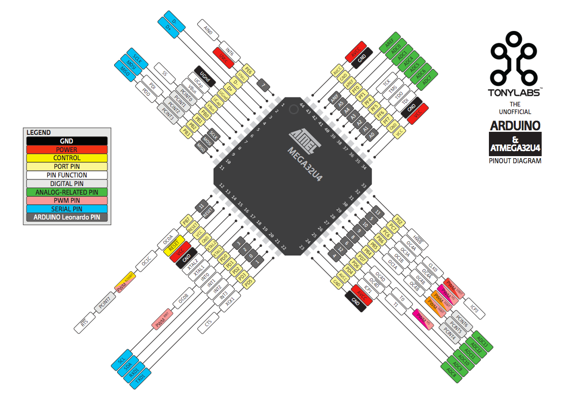
ProMicro uses Atmega32U4, yes? Then for it to be an SPI slave, the SPI master must have access to the 32U4's SS pin, which is PB0, physical pin 8. If it's not broken out to a header pin, wire the pin to an used signal header and use that.
CrossRoads:
ProMicro uses Atmega32U4, yes? Then for it to be an SPI slave, the SPI master must have access to the 32U4's SS pin, which is PB0, physical pin 8. If it's not broken out to a header pin, wire the pin to an used signal header and use that.
What I'm wondering about is that if they omit the SS pin then how we can connect to the SS?
Also, I think if they omit the SS connection, then it would be not so important to connect this pin in SPI operation. I guess!
Thanks for the links but it was so difficult to connect the wiring of the schematic to the actual pro micro pinout.
I have the clone version, like this one:
CrossRoads:
And I missed it - the RxLED/SS pin is pin2 on the J5 header, no wiring needed.
I wrote a code to blink PB0, so the RX LED is blinking and I connected another LED to the other pins of the board and it turns out that the RX and TX LEDs are connected directly from the chip to the LEDs with no sharing to pins.
"it turns out that the RX and TX LEDs are connected directly from the chip to the LEDs with no sharing to pins."
So run a wire from the Rx LED or it's current limiting resistor (buzz out with a meter to see which connects to pin 8 directly) and connect to an IO pin.
You need SS pin access to run the board as an SPI slave, that is clearly stated in the 32U4 datasheet.
CrossRoads:
"it turns out that the RX and TX LEDs are connected directly from the chip to the LEDs with no sharing to pins."
So run a wire from the Rx LED or it's current limiting resistor (buzz out with a meter to see which connects to pin 8 directly) and connect to an IO pin.
You need SS pin access to run the board as an SPI slave, that is clearly stated in the 32U4 datasheet.
OK I understand, but why they didn't connect it to I/O pin? While they know SS is mandatory for SPI operation? Is it that this board isn't intended for SPI operations or what is the principle here of omitting the SS pin from the I/O pins?
wolfrose:
OK I understand, but why they didn't connect it to I/O pin? While they know SS is mandatory for SPI operation? Is it that this board isn't intended for SPI operations or what is the principle here of omitting the SS pin from the I/O pins?
I think this is just bad design.
Like (many) other things with Arduino.
One example only - with older boards: placing the reset button almost in the "middle" of the pcb so there is no way to press it when you have a shield installed...
Like (many) other things with Arduino.
One example only - with older boards: placing the reset button almost in the "middle" of the pcb so there is no way to press it when you have a shield installed...
By the way: I like Arduino
Absolutely
Me too !
Anyway, I'm now working with Uno and Nano boards. Still having problems running default SPI codes in the datasheet.
In the case of the ProMicro you purchased, not breaking out the SS pin was a Sparkfun decision, not an Arduino decision.
"ProMicro Design by Spark Fun Electronics"
One example only - with older boards: placing the reset button almost in the "middle" of the pcb so there is no way to press it when you have a shield installed...
Reset is available on the Power header, so it's always easy to jumper in an external switch if one is needed during development - and that's practically the only time one it's ever needed.
Yes, exactly, it's a Sparkfun board or a knock off of a Sparkfun board if it is a Pro Micro. There has never been an Arduino Pro Micro. Pro Micro is not related to Arduino at all, except it so happens you can program it from the Arduino IDE. Same story with the DF Robot Beetle, just another derivative board designed by some other company.

