SSI - absolute encoder -CS CLK DO

Hi there,
I am new there, and I have some experience with some easy applications with my arduino uno/mega/nanos.
No problems reading an incremental encoder.

Now I would like to use an absolute encoder reading the absolute position of an axis of my optical bank.
No CNC, milling stuff. No sophisticated circuits, only the visualisation of an position, e.g. in serial monitor, later on with a LCD - but this can be excluded here, I think that is not the big problem for me.

So, now I have ordered a 12 BIT absolute encoder with rare information.
It is a magnetic encoder: BRT38-SOM-4096-RT1
360 Degree, non-contact
UPC: 781573936858
EAN: 0781573936858

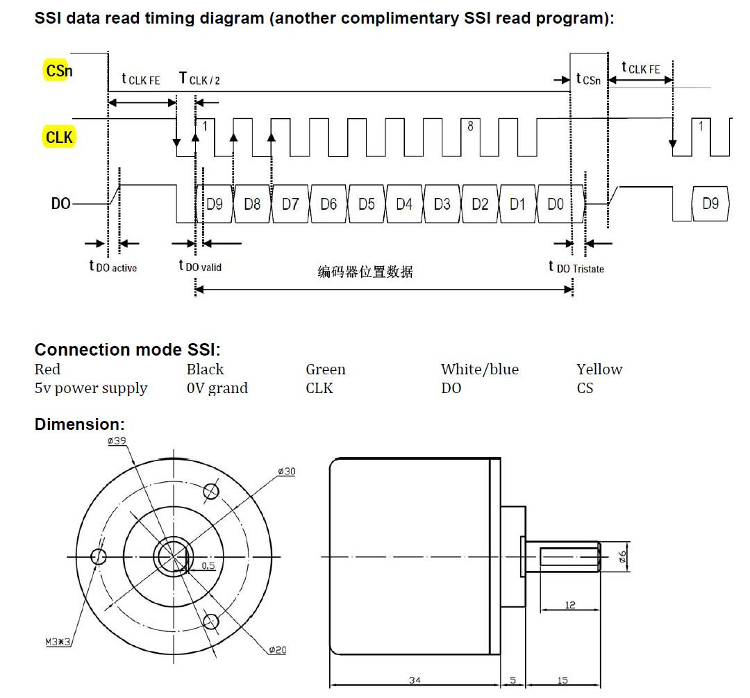
Connection: Red=VCC, Black = 0V, Green =Input CLK, Blue= Output DO, Yellow = Input CS

For the first time I would be happy if someone can tell me, if there are risks for damaging the encoder (I have only one item ordered). e.g. PULLUP for the digital input of the arduino via DO from the encoder.

After searching the net, I found out, that CLK is the CLOCK Signal, an Input to the encoder,
CS an Input to the encoder, too.
DO is the digital output of the encoder, right?

A little bit confusing is the fact, that I read, that I can put it directly to the Arduino, and on the other hand, I need an interface to connect between the encoder and the arduino.

Can you please help me starting on with some code and healthy hints for my hardware?

In the attachment are two images, from the encoder and the info sheet with technical drawing of the signal.

Best regards,
Matthias

This looks like a pretty standard SSI absolute encoder and you should have no trouble reading it with an Arduino. There is a good reference thread here Absolute rotary Encoder SSI SPI how ? - Networking, Protocols, and Devices - Arduino Forum

After searching the net, I found out, that CLK is the CLOCK Signal, an Input to the encoder,
CS an Input to the encoder, too.
DO is the digital output of the encoder, right?

Correct.

With the 16MHz processors, the digitalWrite(CLK,LOW) and digitalWrite(CLK,HIGH) to trigger the DO reading take a few microseconds, and are likely to be within the timing range for the clock signal with no need for delays or special timing.

are risks for damaging the encoder (I have only one item ordered). e.g. PULLUP for the digital input of the arduino via DO from the encoder.

I don't see any. The Arduino and the encoder are both 5V systems.

A little bit confusing is the fact, that I read, that I can put it directly to the Arduino, and on the other hand, I need an interface to connect between the encoder and the arduino.

No interface is required in my experience. I'm not certain where you read information that you might need something, but please provide a reference for review.

Can you please help me starting on with some code

The heart of your program will be reading and assembling the 12 bits to give an integer value. Do you know if you are going to have multiturns? Counting passes through zero and the direction will be necessary.

The reading routine is basically something like this

digitalWrite(PIN_CS, LOW);
//some timing delay maybe required before reading
unsigned int reading = 0;
for (byte i = 0; i < 12; i++) //12 bit reading
{
  digitalWrite(PIN_CLOCK, LOW);
  digitalWrite(PIN_CLOCK, HIGH);
  reading = reading << 1 + digitalRead(PIN_DATA);
}

digitalWrite(PIN_CS, HIGH);

Hi cattledog,
thank you so much. I fear for damaging my "lonely" encoder, thanks for your help!!!
Tonight I will run a test like this code snippet:

const int PIN_CS = 5;
const int PIN_DATA = 6;
const int PIN_CLOCK = 7;

void setup() {
  pinMode(PIN_DATA, INPUT);
  pinMode(PIN_CLOCK, OUTPUT);
  pinMode(PIN_CS, OUTPUT);

  Serial.begin(19200);
}


void loop() {

digitalWrite(PIN_CS, LOW);
//some timing delay maybe required before reading, inserted 1ms in reading section

unsigned int reading = 0;
for (byte i = 0; i < 12; i++) //12 bit reading
{
  digitalWrite(PIN_CLOCK, LOW);
  delayMicroseconds(1);
  digitalWrite(PIN_CLOCK, HIGH);
  delayMicroseconds(1);

  reading = reading << 1 + digitalRead(PIN_DATA);
}

digitalWrite(PIN_CS, HIGH);

Serial.Println(reading);

}

It should output something like that: 100101010011, right?

I will upload my efforts.

Best regards,
Matthias

Hi there,
thank you so much for "ENTRANCE" in this topic.
So, I did some tests, so I can tell you, that the code resulted only "0" as output.
I modified it to:

const int PIN_CS = 4;
const int PIN_DATA = 5;
const int PIN_CLOCK = 6;

void setup() {
  //setup our pins
  pinMode(PIN_DATA, INPUT);
  pinMode(PIN_CLOCK, OUTPUT);
  pinMode(PIN_CS. OUTPUT);

  Serial.begin(19200);
}


void loop() {

digitalWrite(PIN_CS, LOW);
//some timing delay maybe required before reading

unsigned int reading = 0;
for (byte i = 0; i < 12; i++) //12 bit reading
{
  digitalWrite(PIN_CLOCK, LOW);
  delayMicroseconds(1);
  digitalWrite(PIN_CLOCK, HIGH);
  delayMicroseconds(1);

  reading = reading << 1 + digitalRead(PIN_DATA);
}

digitalWrite(PIN_CS, HIGH);

Serial.Println(reading);

}

So I elimnated <<1 to:
reading = reading + digitalRead(PIN_DATA);

This produced changes in the output from 0-9.
So, the encoder is working, and the values are changing when I move the shaft.
But, I don´t know what to do now. Any hints?
Best regards,
Matthias

There may be an issue with the operator precedence so try

reading = (reading << 1) + digitalRead(PIN_DATA);