ST7789 OLED Gray screen problem

#include <Adafruit_GFX.h>
#include <Adafruit_ST7789.h>
#include <SPI.h>

#define TFT_RST   14
#define TFT_DC    27

#define TFT_MOSI  13
#define TFT_SCLK  12

Adafruit_ST7789 tft = Adafruit_ST7789(TFT_DC, TFT_MOSI, TFT_SCLK, TFT_RST);

void setup(void) {
  Serial.begin(115200);

  tft.init(240, 240);
  tft.setRotation(1);
  tft.fillScreen(ST77XX_BLACK);
  tft.setTextColor(ST77XX_WHITE);
  tft.setCursor(10, 10);
  tft.setTextSize(2);
  tft.println("test 10x 10y");
  tft.setCursor(10, 40);
  tft.println("test 10x 40y");
}

when I try this code with esp32, the power comes to the screen and the background turns to a greyish colour. but the colour or text I want is not happening. what is the specific solution for this?

some solutions I tried : I changed the pins, uninstalled and reinstalled the libraries.

Show a drawing of the project, and a picture. Verify your screen has the ST7789 chip.

I can send photos of the project. I shared both the state in the circuit and the text behind the screen.


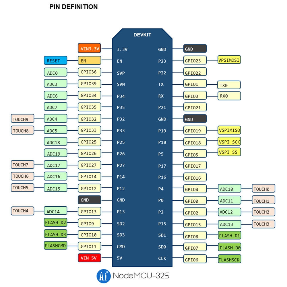
You should make a connection drawing. The picture of the back of the card (screen) is good. It looks like the card is I2C (using SDA and SCL) but your code looks like it is looking for SDI (MOSI, MISO, CS, SCK). Check the documents for the card (screen)

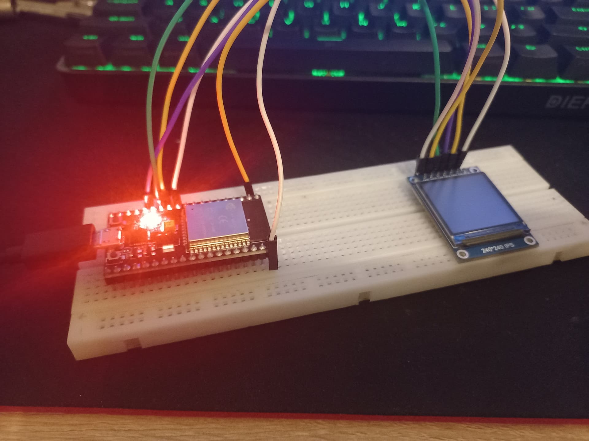
The picture of the breadboard is useless. Make a drawing (easy), or post a picture showing all the wires and pin numbers (not easy).

Thanks for the advice, tomorrow, I will look at the documentation and make a drawing as you say.

Have you tried the example provided in the library? (can't tell if you code is the example)

Try connecting the hardware SPI pins to your display, I believe that would be as follows

ESP32 SPI MOSI PIN 23 to the display SDA
ESP32 SPI SCK PIN 18 to display SCL

adjust the code at the top of the form to read as follows

#include <SPI.h>
#include <Adafruit_GFX.h>  
#include <Arduino_ST7789.h> 

#define TFT_DC    27
#define TFT_RST   14

Arduino_ST7789 tft = Arduino_ST7789(TFT_DC, TFT_RST);

keep everything else the same and see if if gives any results.

EDIT: I should clarify that when I say PIN 23 and 18 on the ESP32 I mean GPIO23 and GPIO18

Do you have the header pins soldered onto the display board? I cannot tell by looking at the picture.

i try it .ino file something like graphictest.ino but same problem keep

i try it but its not working again same problem but, when i press power button its debug like

rst:0x1 (POWERON_RESET),boot:0x3 (DOWNLOAD_BOOT(UART0/UART1/SDIO_REI_REO_V2))
waiting for download
ets Jul 29 2019 12:21:46

also I found thisand placed it accordingly. Because the esp32 I have unfortunately does not have pin number names.

I did not solder it, because I want it to remain as a prototype for now. so I temporarily hold the holder sent by the manufacturer and I can see the greyish colour on the screen.

All pins require good connections.

sooo my problem is basically that im not soldering?

This is possible, and probable. The holes (vias) are round, the pins are square. At best the pin-to-via contact is very small. The small contact increases resistance. and Ohm's Law (V = IR) says if voltage remains the same and resistance increases, current decreases.