Hi,
I have an Arduino UNO with a ST7920 LCD connected to it in 3-wire SPI mode.
This is the class I am using for it.
U8G2_ST7920_128X64_1_HW_SPI u8g2(U8G2_R0, 10, U8X8_PIN_NONE);
Pin 10 is my chip select. The other two pins the LCD uses are 13 and 11 for SPI.
The LCD is working nicely, however I also have a Seeed CAN shield and when I am trying to read data from the CAN device I see two lines being drawn across the LCD. Almost as if the LCD is processing the data when I talk to the CAN shield over SPI.
The CAN shield uses pins 13 (SCK) and 11 (MOSI) as well for SPI.
Note that pin 10 (CS) is not used on my revision of the CAN shield (it instead uses pin 10).
Would anyone be able to help me figure out why this is happening? From what I've read online after doing some searching it seems that these LCD's have broken CS state. If this is the case, does anyone have a work around??

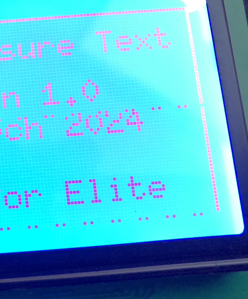
Here is what the LCD is doing. Note the dual-dotted lines above "2024" and below "Elite". This happens when I'm trying to read from the CAN shield.