Hello, I work on project with an Industriano and an Arduino. I use a programable tension analog pin for sending information to my Arduino. My Ardruino read an analog pin and convert this tension in deplacement. I have a probleme with the stability of my reading analog value. My voltmeter indicate a stable value (0.035 volt at 0mm).
Can you help me?
Thank.
The standard way to take a stable reading is to take several in succession and to use the multiple readings to derive a value by averaging them, perhaps after removing the highest and lowest values to eliminate obvious outliers
Are you reading one analogue pin or a series of them, because you may need to allow settling time between reading each pin in addition to taking several readings
The voltage is probably too low to get useful readings.
How unstable is it? What's the maximum voltage you need to read?
A capacitor between the analog input and ground (maybe 0.1uF) should also help if you are picking-up analog noise.
The default ADC reference is Vcc (usually 5V) so any noise or variations on the 5V power supply will cause noise/variations in the readings.
The Arduino's ADC is very-stable, accurate, and linear. It think it should be stable +/- 1 count. With any analog-to-digital conversion you can be on the "hairy edge" between counts and it can jump. back-and-forth.
The standard 10-bit ADC with a 5V reference means about 5mV (0.005V) per-count and when you're reading 35mV that may not be enough resolution and too much error, and if it's jumping by 1-count it's jumping by 5mV.
If you can use the internal 1.1V reference it's very stable and you can get about 1mV resolution. (But the internal reference isn't necessarily accurate. I think it's +/- 0.1V, so you may have to make a calibration correction in software.)
If your input voltage sometimes goes over 1.1V it's possible to automatically switch between references for more resolution when the voltage is low (like an auto-ranging multimeter).
I am replying to this topic after looking at 50+ topics on searching for analog stability topics. I think this topic is the most similar to my issue.
Issue: My analog readings, both Arduino AI and Arduino DI are fluctuating.
My own conclusion: I shouldn't worry about it since it does not affect my code output.
Hello Bob, if you read this.
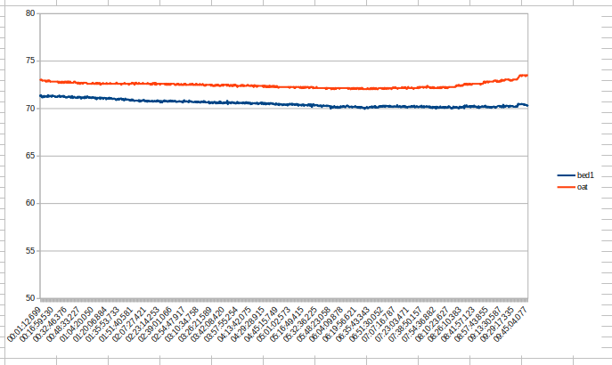
I have noisy readings on my arduino sensors, both thermistor and DS18B20. The noise (not the correct term, I know, but the signal jumps up and down.) It was jumping more than 1 degree fahrenheit +/- so I sampled the signal 20 times as suggested above. The jumping reduced to much less. The final result is as shown below for the thermistor, marked Bed1. The DS18B20 was not sampled, results below marked oat. I also tried various capacitors on the analog input. (not the DS18B20 digital input.) The capacitors did no good. The sampling averaging smoothed out the readings on the thermistor to +/- .1 to .3 or so. So I should be happy, I guess. I am getting no false relay chatter by using the analog values in my program to output to a relay. So, no big deal, I guess, if the graphs are jittery. I still remain curious why the jittering, just like the original poster was curious.
// program for Bed1, ground level apartment
  float total1 = 0;
  for (int i = 0; i < 20; i++) {                      // take 20 readings and average them to smooth readings, typical.
      Vo1 = analogRead(Bed1ThermistorPin);
      R2z1      = R1s1 * (1023.0 / (float)Vo1 - 1.0);
      logR2z1   = log(R2z1);
      read1 = (1.0 / (c1 + c2*logR2z1 + c3*logR2z1*logR2z1*logR2z1));
      delay (interReadingDelay);
      total1 = total1 + read1;
  }
  average1 = total1/20;
  Bed1T    = average1 - 273.15;             // Kelvin temperature converted to Celsius
  Bed1T    = ((Bed1T * 9.0)/ 5.0) + 32.0;  // Celsius converted to Farhenheit
code for DS18B20
// the following lines are for the ninth sensor, DS18B20. I needed 9 sensors and the Arduini Nano only had 8 AO inputs
#include <OneWire.h>                      // the DS18B20 uses a digital input pin instead of needing an analog pin
#include <DallasTemperature.h>

// Data wire is plugged into pin 11 on the Arduino
#define ONE_WIRE_BUS 11

// Setup a oneWire instance to communicate with any OneWire devices
// (not just Dallas temperature ICs)
OneWire oneWire(ONE_WIRE_BUS);

// Pass our oneWire reference to Dallas Temperature.
DallasTemperature sensors(&oneWire);
float sensorread = 0;
//end DB18B20 program

void setup() {
  Serial.begin(9600);
  // Start up the DB18B20 sensor library
  sensors.begin();

void loop() {

  sensors.requestTemperatures(); // Send the command to get temperature from ds18b20
  Serial.println (" Hydronic Computerized Control System");
  Serial.print(" Outside Air Temperature:   ");
  sensorread = ((((sensors.getTempCByIndex(0))*1.8)+32));
  Serial.println(sensorread); // Why "byIndex"?
    // You can have more than one IC on the same bus.
    // 0 refers to the first IC on the wire