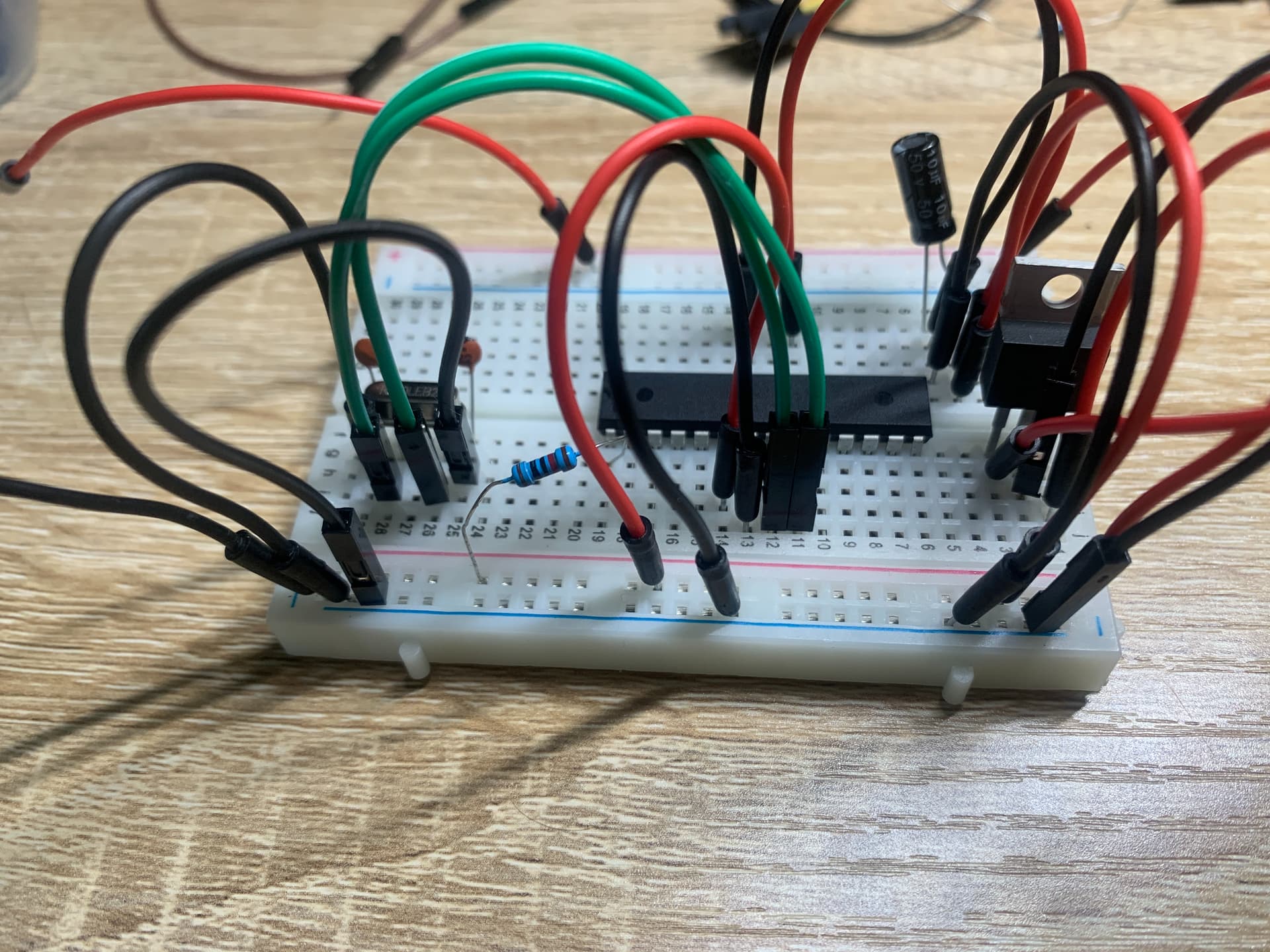
Oh, hi everyone. Hopefully a simple question here. My standalone ATmega 328p is drawing significantly more current than I anticipated. When the same chip is mounted on an arduino uno it pulls roughly 40mA. However, my "bare minimum" standalone set up draws 800mA.
There is something very very wrong if that is actually drawing 800mA. Something should be getting real hot. I am with @red_car, how are you measuring that?
Missing from your circuit are the two 0.1uF bypass caps, one from Vcc to ground and another from AVcc to ground. They are required and the 10uF bulk capacitance in no way makes up for them.
I was definitely worried something was getting fried. Nothing seems to be getting hot, though. I'll make the recommended changes and look up correct crystal wiring.
I have the rest of the circuit in series with my meter. Like this:
I'm just using a 9V battery, which shows 8.8mA on a 1k resistor. So, a functioning meter plus nothing getting hot... does that mean there has to be a short somewhere? I've stared at this thing to no end and cannot seem to find one.
That 5V regulator ground pin couldn't be the culprit, could it?
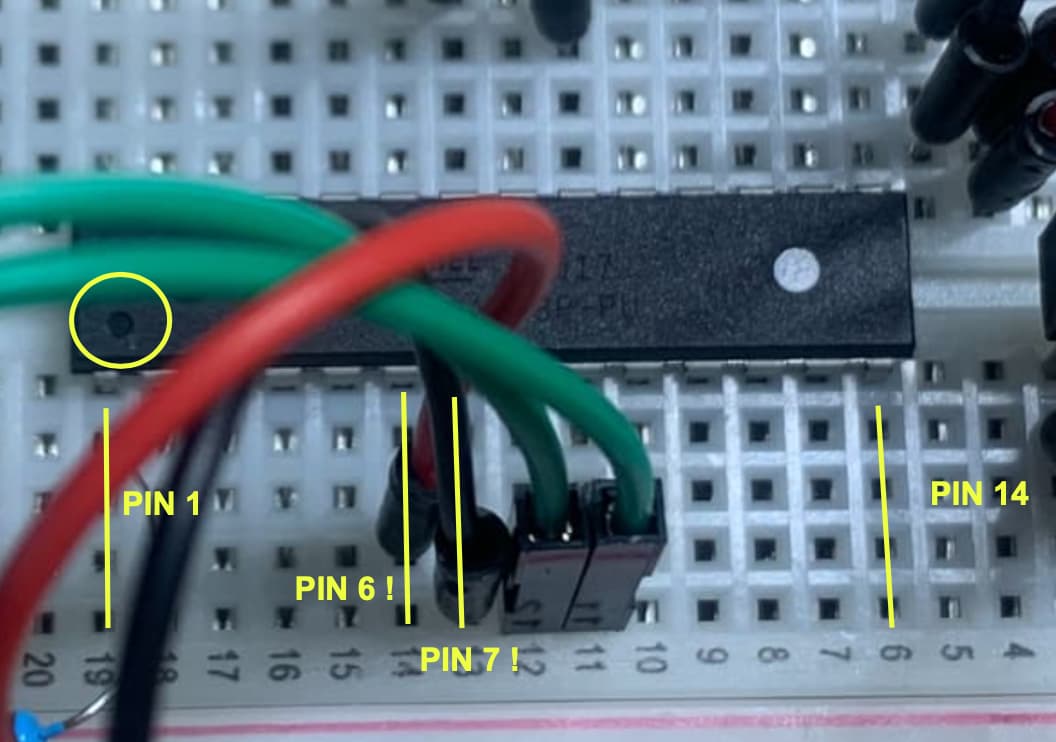
If you have the wiring as indicated in the picture the crystal looks fine to me. Maybe @Paul_B can tell us what is wrong, I am sure missing it.
I am currently using a setup with exactly the same basic wiring, not the same layout of course, and it is working fine. I do power from the USB and not via a 12V supply and regulator.
I have my Atmega32U4 ISP programmer, Atmega328P, ATTiny1614, MCP23017, PCA9685 servo board and a 20x4 LCD display with I2C backpack all hanging on the USB port. My cheapy inline USB amp/volt meter says I am barely touching 80mA.
How about showing us a picture of YOUR layout, maybe we can find something.
Really appreciate all the time and brainpower thus far, everyone.
I tried @red_car's suggested and pulled some wires. Findings are:
-Removing positive rail -> VCC reduces draw to 530mA
-Removing capacitor -> AVCC reduces draw to 580mA
-Removing chip -> GND reduces draw to 10mA
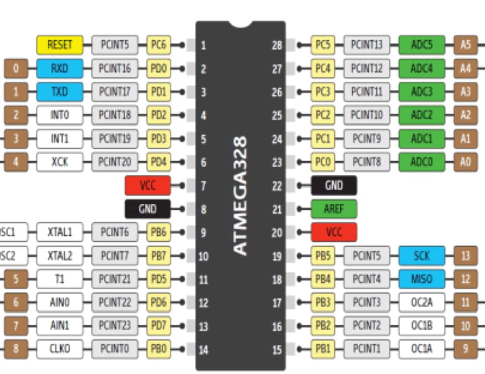
Does this mean the circuit is somehow shorting through GND? I see with this diagram the chip is wired to GND twice. I have quadruple checked based on this diagram and others that I'm using the right pin.
Also, the 9V battery is just a standard Duracell, although thanks for the knowledge of the smoke alarm batteries. Didn't know there was a different type.
Now, the blink test:
-I put the chip back into my Uno for programming. The onboard LED seems not to be functioning (news to me) so I switched the sketch to pin 4 and wired in an external LED. Works fine in the Uno.
-Back on the breadboard: With that GND pin plugged in, nothing happens, still drawing ~800mA.
-With the GND unplugged, the LED stays on solid.
I fear now that I've foolishly burned out pin 4, since I can't replicate the solid LED result. I checked the LED on its own circuit afterward, it's still functioning, not burned out.
Your photos don't show the 0.1uF (100nF) decoupling capacitors that were suggested by @groundFungus back in post #3. The regulator (7805?) usually has capacitors between Vin & Gnd and Vout & Gnd as well.
Edit: Do you have another Arduino board to hand - maybe an Uno, that you could take 5v from to temporarily power your breadboard project and get the simple blink sketch working. Remove the regulator from your breadboard first.
I wouldn't attach an 800 ma load to another Arduino. If that current is real(which I doubt, as you'll not get that from a 9V duracell for long, so maybe your meter's decimal isn't working???), you could just make another piece of junk out of the new Arduino.
Instead, start by doing ONLY one thing - removing the IC. At that point, you should be able to measure just the quiescent current of the 7805 itself.
Let us know how that goes.
C