I want to power an Arduino from a solar rechargeable battery pack I have. The problem is that the pack cuts of power after a few seconds of being idle.
So on startup the servo spins of course, as it scans to 180 and returns to 90. I come back after an hour and nothing has happened. The arduino led is off.
If your power pack is a backup cell phone charger, it will switch off when the current falls below a certain level, it thinks the phone is full charged and won't overcharge it, try a 1/2 watt 100 Ohm resistor across the + and - rails and see if it stays on.
You may have to go as low as 27 - 33 Ohms but watch the resistor wattage, may need a 1 watt.
Ok, I just happened to take apart a UPS power unit from Tripplite and just happened to find a 47Ω resistor in there. So I plopped it on a breadboard and it works, the battery doesnt standby anymore. So why does this happen?
When the phone is fully charged, no current is drawn from the charger, so it shuts down. A fully phone charged presents a large resistance which tells the charger not to push anymore energy out so it shuts down?
And then when we put the 47Ω resistor bridge between the -/+ charger terminals, it suddenly only has a small 47Ω resistance, so it starts pushing out current?
Your assumptions are pretty much correct, problem with your fix is the resistor constantly wastes 530 mW, I wrote a simple sketch to pulse the resistor periodically to keep the power bank from timing out, I found that a 50 mS pulse through a 56 Ohm resistor every 15 seconds would keep mine alive:
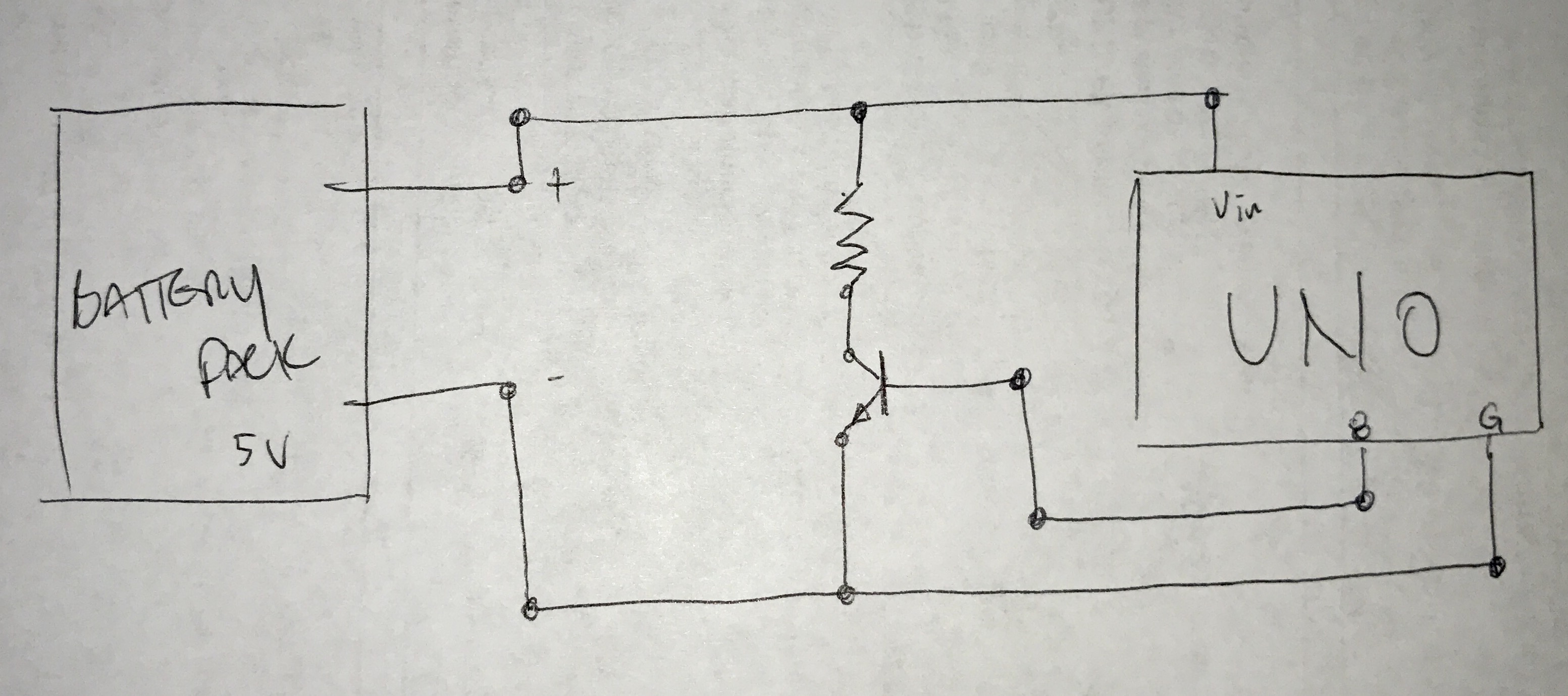
Yes, but the 5V goes to the 5V pin, the VIN pin needs at least 7V to produce a 5V output. Don't try to drive more than about 750 mA into the 5V pin, the circuit board traces might overheat. Also, be cautious when plugging in a USB cable, if the power pack voltage is too high it may feed back into your PC and damage it, make sure the power pack voltage is well regulated 5V.
The voltage from the battery pack is 5V. I always forget the differences between the 5v pin, the Vin, the barrel jack and the usb jack. Ill read up on that again.
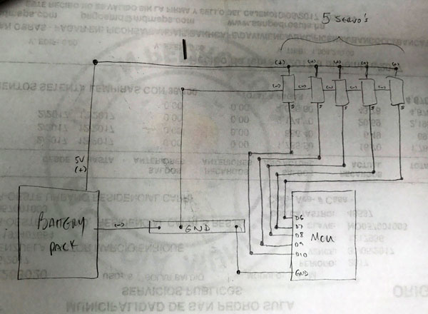
As for the current draw, right now the project is just a MG995R servo and an LCD. But in the future the project is supposed to grow to an MCU with its LCD running 4 to 8 servos, not simultaneously though. Servo1 would run for 1 minute and stop, a couple of minutes later Servo2, and so on. So it would not be drawing current for all at the same time. But if I wanted to eventually connect 3 servos that would run simultaneously and I know now that I cant pull more than 750mA from pin 5V, I would set it up to run the servos separately from the mcu.
Well i plugged it all in and didnt upload the code for the pulses, but the pack is not turning off. I think its because the servo keeps humming after stopping. Do I need to detach it or something?
The servo moves fine but after reaching the desired position it stops and holds there, but as it holds, it hums. Im guessing this is just wasting energy.
Your drawing looks fine to me but you need a VCC (5V) wire if not powering from USB.
Many cheap low cost servos do that, I guess that's the cost of "economically priced" , sometimes a little spring force or something will muffle them or mount them on something solid that doesn't resonate like a guitar body.
If you detach, you should save the current position so you can write it back before reattaching (as long as the servo is not moved while detached):
currentPos = servo.read();
servo.detatch();
// and later,
servo.write(currentPos);
servo.attach(Pin);
Ok while I get this tested, (Im re-charging my lipo before I test the new code with servo detach and pulse code), I noticed that the LED lights for rx/tx on the nano remained lit throughout my delay of 1 hr with the old code. Why would that happen?
Here is the code:
#include <LiquidCrystal.h>
#include <Servo.h>
Servo servo1;
//Servo servo2;
int servo1pin = 8;
int servo2pin = 9;
int angle1 = 0;
//int angle2 = 0;
float tempVoltage=0.0;
LiquidCrystal lcd(12, 11, 5, 4, 3, 2);

void setup(){
  lcd.begin(16, 2);
  lcd.setCursor (0,0);
  lcd.print("Koffee Servo");
  lcd.setCursor(0,1);
  lcd.print("Lipo Test");
  delay(1000);
  Serial.begin(9600);
  servo1.attach(servo1pin); ATTACH IN LOOP
}

void loop(){
  servo1.write(angle1);
  // Servo #1 ~ 2.5 secs
  for(angle1 = 0; angle1 < 180; angle1++)  {
    //Serial.println(angle1);
    servo1.write(angle1);
    delay(50);
  }

  //Read/Display voltage & wait
  readVoltage();
  delay(3600000); //3600000~ 1 hr

}


void readVoltage(){
  int analog_val=analogRead(A0); // read A0 and store it in analog_val
  tempVoltage = (analog_val * 5.0)/1024.0;
  lcd.clear();
  lcd.setCursor(0,0);
  lcd.print("V=");
  lcd.print(tempVoltage); //print v to LCD
}
Ok I uploaded this code to my nano but its not working:
#include <LiquidCrystal.h>
#include <Servo.h>
Servo servo1;
int servo1pin = 8;
int servo2pin = 9;
int angle1 = 0;
float tempVoltage=0.0;
LiquidCrystal lcd(12, 11, 5, 4, 3, 2);

//Pulse code for lipo alive
unsigned long iStart; // interval start
const unsigned long iEnd = 15000; // interval end
const int pLen = 50; // pulse length
const byte pPin = 7; // pulse pin

void setup(){
lcd.begin(16, 2);
lcd.setCursor (0,0);
lcd.print("Koffee Servo");
lcd.setCursor(0,1);
lcd.print("Lipo Test");
delay(1000);
pinMode(pPin,OUTPUT); //pulse pin
Serial.begin(9600);
}

void loop(){
servo1.attach(servo1pin);
servo1.write(angle1);
for(angle1 = 0; angle1 < 180; angle1++)  {
  //Serial.println(angle1);
  servo1.write(angle1);
  delay(50);
}

servo1.detach();
keepAlive();
readVoltage();
delay(3600000); //3600000~ 1 hr
}

void keepAlive(){
Serial.println("pulsing");
digitalWrite(pPin,millis() - iStart < pLen);
if(millis() - iStart > iEnd)
  iStart += iEnd;
}

void readVoltage(){
int analog_val=analogRead(A0); // read A0 and store it in analog_val
tempVoltage = (analog_val * 5.0)/1024.0;
lcd.clear();
lcd.setCursor(0,0);
lcd.print("V=");
lcd.print(tempVoltage); //print v to LCD
}
The connections are as were suggested. Im using D7 off the nano to send a pulse through a resistor to a 2n2222 transistor, out to GND and 5V from the battery:
You say a 50ms pulse every 15 seconds through a 56Ω resistor kept yours alive but you have a 1k R to the base of the 2n2222. Im confused then, did you mean the dummy load is your 56 Ω resistor?
So I checked other posts on the web and the 56 is the dummy load, Im using a LED. The 1k resistor is at the base as explained. However my battery pack keeps turning off. It has its own set of leds that it uses for 2 purposes:
Displaying all 4 blue showing its active or in use.
Displaying state of charge in red.
I turn on the battery pack by pressing a button it has, it activates as shown by the 4 leds in blue. The nano and my lcd power up and start to work as expected. 10 s later, the 4 leds blue on the battery pack turn off but the nano and lcd are still on. 20s after that the nano and lcd power down completely.
OK yesterday I checked the LED that I have as a dummy load and flipped it since I had it on wrong. The LED would Pulse as it should and nano/lcd worked fine for at least an hour until the LED stopped blinking. It almost looked like it was dimmed a lot but because nano/lcd still worked I let the experiment run and it ran for quite a few hours until this morning when for some reason it had stopped working. The nano/LCD and the blue lads we're all off however the battery pack is still pretty well charged at 5.08 V so something else must have happened, possibly the LED started fine but burnt out gradually.
What I would like to understand is if the code is set to send a pulse from the pin to the battery pack as if something were drawing current from it, I'm not entirely clear as to why we need the LED. But it seems the led burning out is indeed related to the problem.
This thread seems to be drifting off toward Never-Never land so lets start over and first find out the minimum current that will keep your power pack alive. Make sure it is full charged, then connect it to a bare breadboard, + wire to the red rail and - wire to the blue rail, put a 180 or 220 Ohm, 1/4 or 1/2 watt resistor across red and blue rails and see if the power pack stays on, if not, add another of the same resistor in parallel with the first and try again, keep adding resistors until the power pack stops shutting off automatically. Report back with how many resistors of what values and we can go from there.