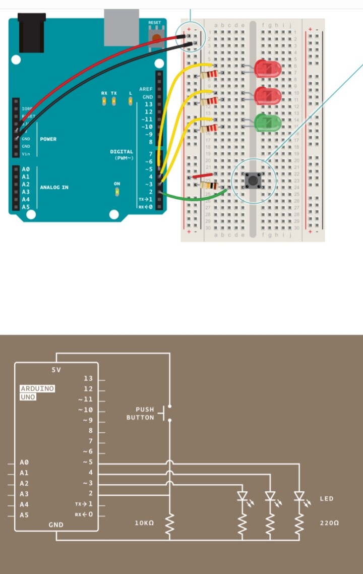
Hi, this is my first question as a new user. Project 01 in the Arduino Starter Kit went great. Project 02 did not. Specifically, the green LED in Project 02 Figure 1 did not light when the input to the anode came from pin 3 (Project 02 Figure 1). It did light up when the input to the anode came from the power bus (as in Project 01 Figure 5, swapping a green LED for the red). I tried using other pins. No other pins made the green LED light up either, except pin 12, which made it slowly flash on and off. What does this situation indicate?
Show the circuit drawing from the project and post the code (text), too. Thank you.
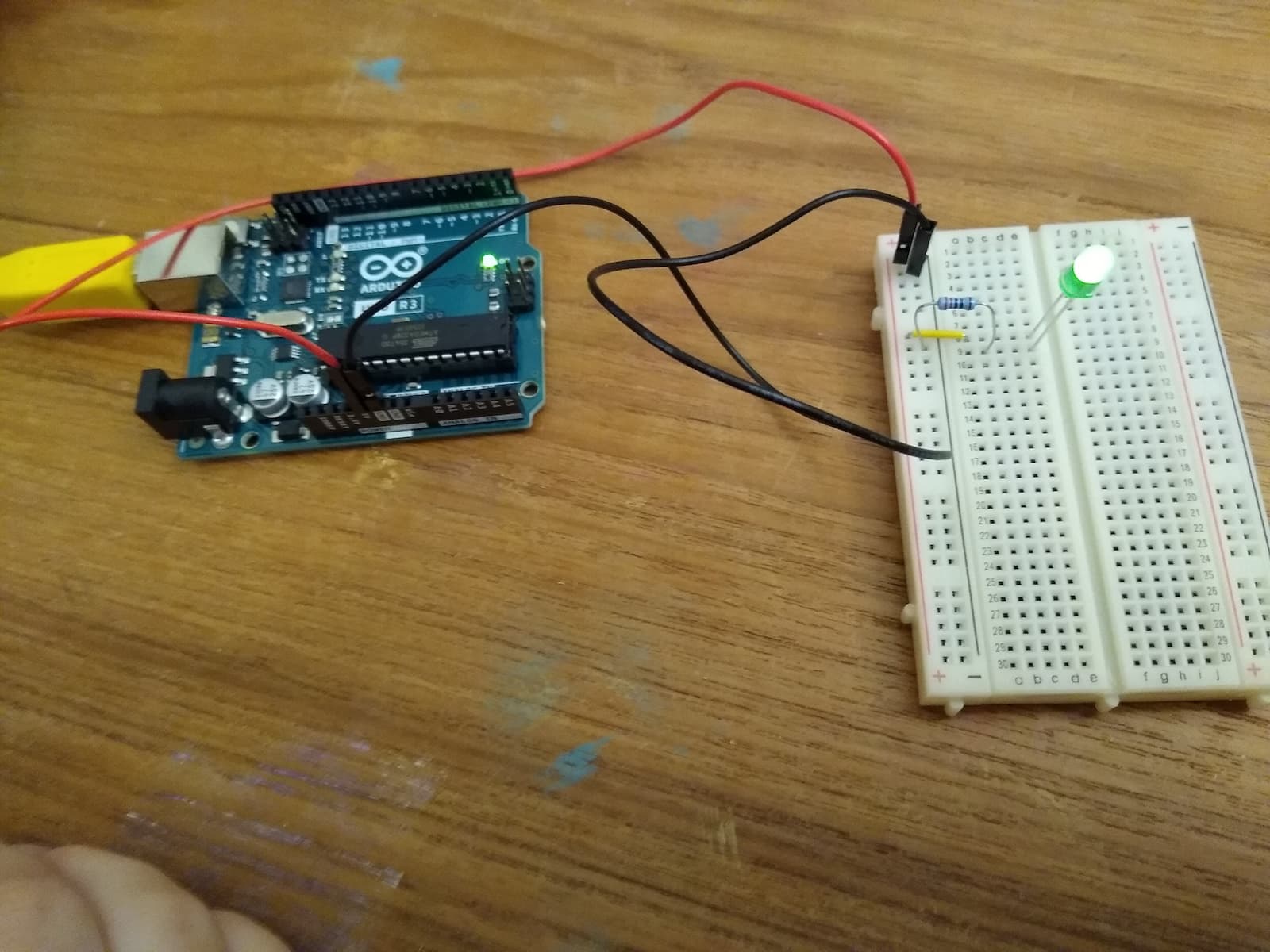
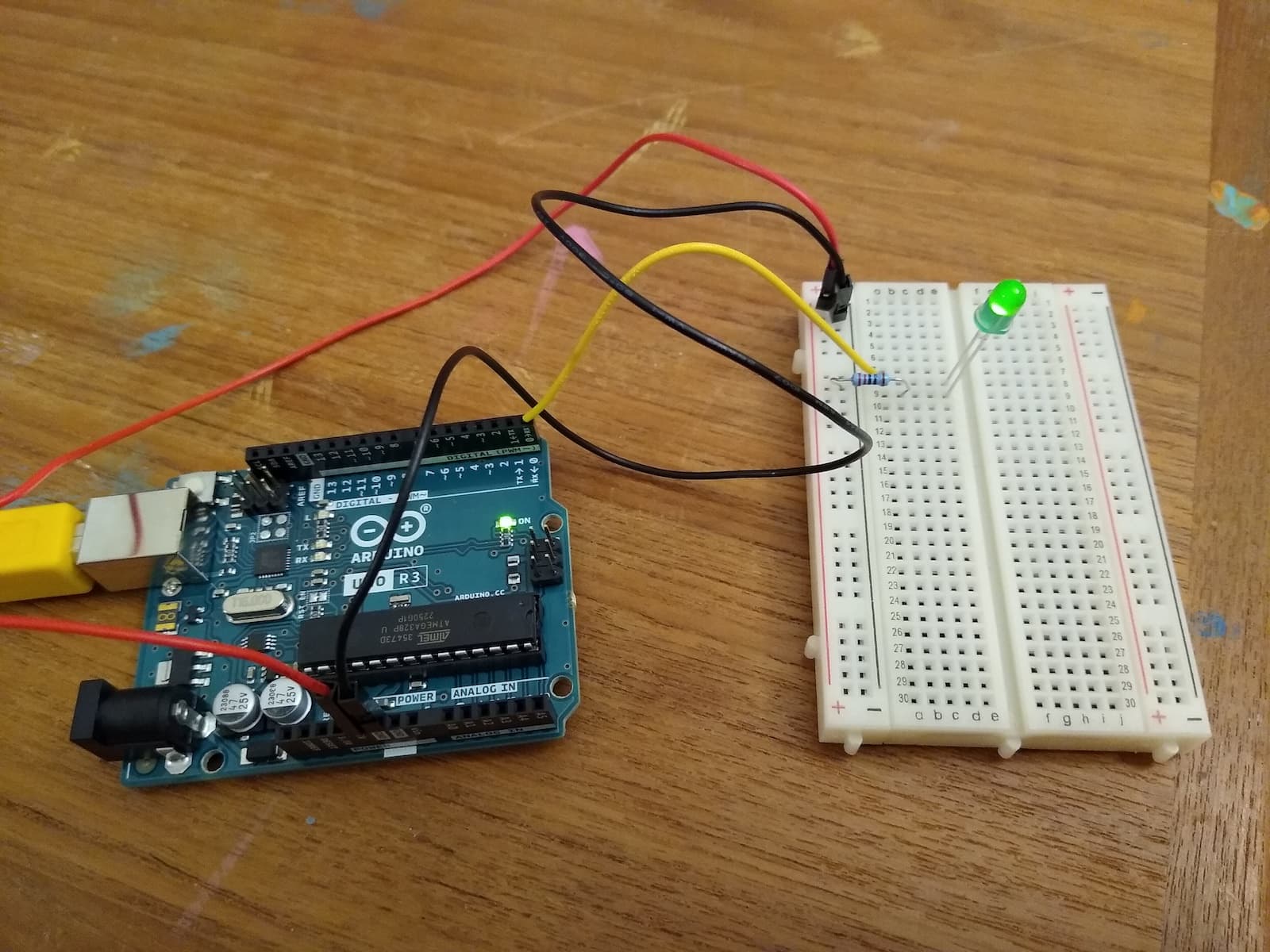
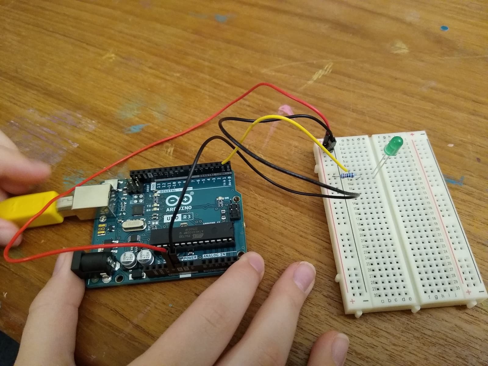
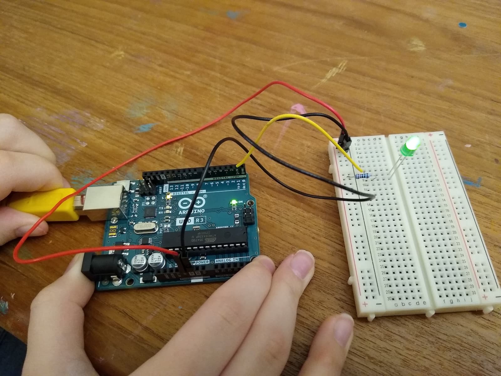
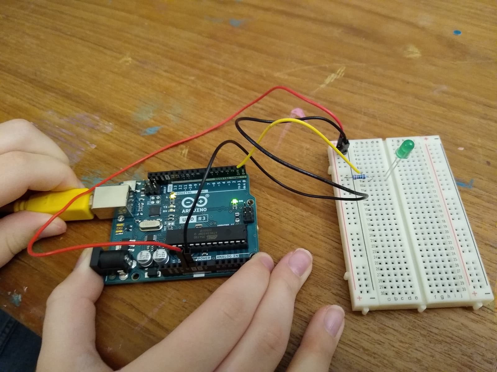
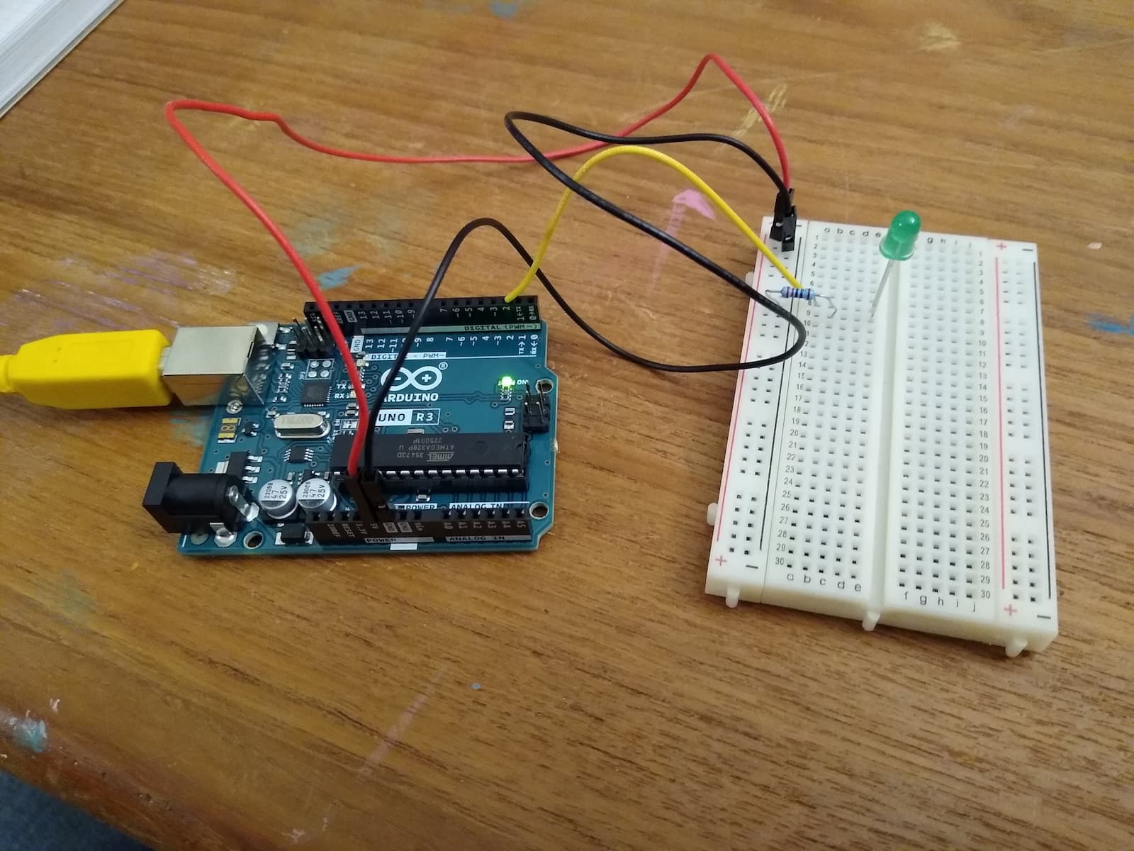
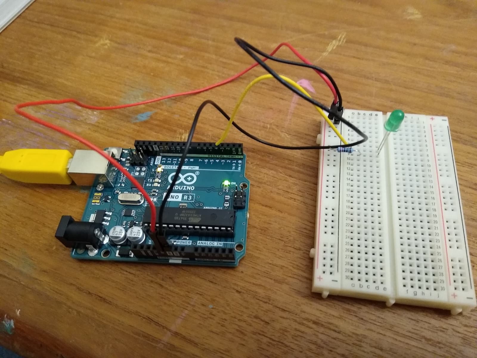
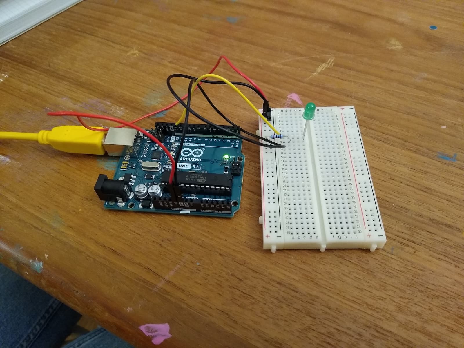
A well-lit close image of your breadboard could also be helpful.
It may be related to bad breadboard contacts. Move the LED to a different row and try again.
If you have a multi meter and know how to use it then measure the voltages on entry (resistor), LED anode and cathode, and find out where the circuit is broken.
Thank you xfpd, dougp and DrDiettrich for your clear and informative help. We (my daughter and I) did a series of tests that to me seem to indicate the pins.
A) Power bus lights LED brightly
B)
C-3) When the USB cable is fully connected, Pin 1 does NOT light LED any more. Pin 1 lights LED only when the USB cable is partly connected (see test C-2).

You need to upload the code. Read from pages 36 - 40.
G) Pin 5 does not light LED. I am not attaching photos for Pins 5-12 because it is repetitive, but we took the photos and can supply if requested.
--> Note that in all tests where I stated a result as "Pin N does not light LED", that outcome held no matter how completely or incompletely the USB cable was attached.
--> Note also that Pin 13 produced a different result. I will attach two photos for Pin 13.
H) Pin 6 does not light LED.
I) Pin 7 does not light LED.
J) Pin 8 does not light LED.
K) Pin 9 does not light LED.
L) Pin 10 does not light LED.
M) Pin 11 does not light LED.
N) Pin 12 does not light LED.
O-1 and O-2) Pin 13 lights LED in long flashes on and off. I didn't measure but probably half a second on, half a second off, repeating indefinitely.

Summary questions -
Why does Pin 0 light the LED dimly instead of brightly?
Why does Pin 1 light the LED only when the USB is partly connected?
Why do Pins 2 through 12 not light the LED?
Why does Pin 13 make the LED flash on and off?
Karma, thanks. Your conclusion is right, we didn't read to there. Looking at pages 36-40, I am wondering if the answers to my summary questions (post #15) will involve differences in default modes between various pins if the user has not configured the pins using the PinMode function. Am I on the right track?
Pins 0 and 1 are the receive and transmit pins for serial communication. They are indirectly connected to the USB data lines. Avoid them for now unless instructed to use them.
Did you type in the code and upload it?
You are most likely running the Blink code
On Edit: I skimmed through the project manual up to Project 2. You uploaded the Blink sketch on page 18. Pin 13 is directly connected to the "L" LED on the board. This is why Pin 13 blinks your LED.
The "L" LED is also referred to as "LED_BUILTIN". Or shall I say Pin 13 has been defined as "LED_BUILTIN".
pinMode(LED_BUILTIN, OUTPUT); as found in Blink is the same as pinMode(13, OUTPUT); LED_BUILTIN and 13 are interchangeable on your Uno.
1 Like
You seem to have uploaded a Blink sketch. No wonder that the other pins don't work.
Not plugging in/out USB properly can result in random (meaningless) behavior. Don't do it.
This topic was automatically closed 180 days after the last reply. New replies are no longer allowed.