Hello,
I'm doing a project that includes 9 servos sg90 (each drawns max 1A). I have 4x 18650 batteries and want to connect them in paraller and series at the same time. That way I get 7,4V and around 20A. Will this step-down converter work?
I've watched this guy, that tests this exact converter. I see that it is not efficent when using high amps. But all I want is it to work.
I'm concerned about Amps IN and OUT. I am taught that, the device will not draw more current than it needs. So when I connect 20A as Input, only max 8A will go through the converter?
Forgive me simple this question.I'm a beginner. Cheers!
Here's scheme of the connection.

Gooday to you.
Looks like your 9 servos could het up to 9A of current draw.
That device has max 8A so there is little to no headroom there. I recommend a higher (I like +20% headroom) current handling minimum 12A.
Technically you could use only some of the servos at any given time and not go over the 8A but that is your own risk.
I have used multiple servos together powered by whats known as a BEC in the radio controlled world. Stands for Battery Elimination Circuit. You can use those too.
I personally have a 20A rated BEC that has adjustable output voltage of 5V, 7.4V etc via jumper leads if those things opens up your options.
Also, to simplify things you could use a single 7.4V 2S Lipo battery instead of those 4. But thats personal preference.
One time, I'm ready to place my order, but I want to be 100% sure that parts that I've chosen will be suitable.
On his auction, this guy also has this 20A converter, which is of course more expensive (I want to cut all the costs to neccesary things).
I've been thinking for over a week what power supply will be best.
I also thought of temperature measuring. I want to use Thermistors placed close to heat sinks and a buzzer, to prevent device from overheating. But honestly, servos won't work longer than 10 min straight at once (small project, just for fun).
You wrote:
"I also thought of temperature measuring. I want to use Thermistors placed close to heat sinks and a buzzer, to prevent device from overheating. But honestly, servos won't work longer than 10 min straight at once (small project, just for fun).".
Be sure to factor in the time delay for the heat from your device to get through the heatsink and be registered by the thermistors. If you don't, the device being cooled will be dead by the time your buzzer go off!
Better to put the thermistor right on the device, itself.
Paul
Paul_KD7HB:
Better to put the thermistor right on the device, itself.
Thank you Sir, but that what I was going for:)
Here's an update. I've done a lot of research, it's 3 a.m. right now and I can not stop thinking.

I'm still concerned about powering the servos.
One 18650 cell gives me ~8.5A (when I measure it with a multimeter I feel hot, and I'm scared It will blow up, because it is from a cheap powerbank)
I want to kindly ask you to watch HOW I MEASURE AMPS AND VOLTAGE OF 2 CELLS
Because, I don't think It is right.
I connect 2 18650 cells in SERIES, which should only increase the voltage. But it increases both the voltage and the current. I know it is a basic question, but it is after 3 a.m. and I'm certainly not thinking straight. First I measure the AMPS and then, the VOLTAGE.
LINK to the video from google drive
In terms of powering the servo
I don't see reason to go for 4 of these cells. I will only use two of them connected in series using this box.
So here's the thing, that I've just learned:

My specs:
U1=8V
I1=16A
Want:
U2=6V
Get:
I2=12A
Is it fixed or can I regulate the amps that I can get on the output?
Am I doing it correctly? Have I gone crazy?
Thank you guys.
Update after almost 2 months.
I'm at the finish of the project.
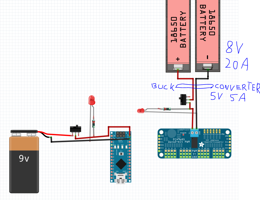
In terms of power supply I use 2x 18650 batteries which gives me around 8V. I got this buck converter which is set for 5V 5A output.
I have a question concerning the two LED Diodes. I have 2 toggle switches:
-one for 9V power battery which's going to power arduino (i'm going to connect 9v battery to the VIN pin)
-one for the power supply of the servos
I want the led to indicate if the switch is switched on. Will this schematic work?
I'm afraid of the high current on the right side.
What resistors should I use? How can I manage to do that?