PaulS:
Someone have a Sketch that i can use to modify?
There was one in reply #7.
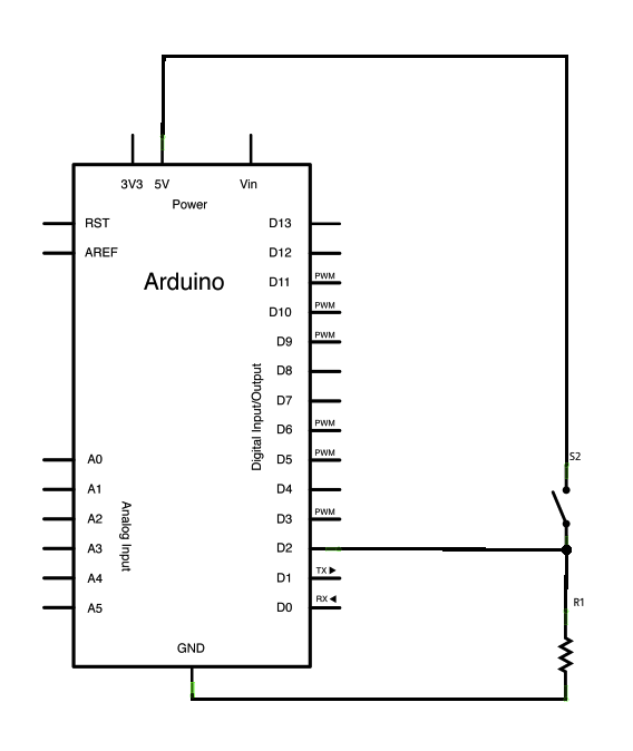
Your problem breaks down into several parts -reading the state of the switch accurately (which requires that it be wired correctly), doing something when the state of the switch changes (not IS something), and making the steppers move correctly to match the effect of the switch press(es).
Which part(s) are working correctly? Which parts are not? Doing something with n switches is not really more difficult than doing something with one switch.
The ( 2 ) 10kOhm resistors are on the way, so i can't realy test my code atm.

This is what i have atm. ( changed from a code i found )
// 4 wire bipolar stepper motor driver code for L293D which controlls the direction of the motor with two push buttons for each clockwise and counter clockwise direction. After completing the predefined steps in 'motorstep' waits for the new direction command will come from one of the push buttons

const int CW = 2;
const int CCW = 4;
const int ENA = 8;
const int ENB = 13;
const int wit = 9;
const int blauw = 10;
const int paars = 11;
const int geel = 12;
int valA = 0; // counter clockwise button vallue
int stateA =0; // state of the counter clockwise button
int valB = 0;  // clockwise button value
int stateB = 0; //state of the clockwise button
int pause = 10; //delay between each step for slow rotation
int motorstep = 48; // number of steps when the buttons are once pressed

void setup(){
  pinMode(wit, OUTPUT);
  pinMode(blauw, OUTPUT);
  pinMode(paars, OUTPUT);
  pinMode(geel, OUTPUT);
  pinMode(CW, INPUT);
  pinMode(CCW, INPUT);
}

void loop(){
  valA = digitalRead(CW); //reads the CW button value and writes to 'valA'
  if(valA ==HIGH){
    stateA = 1- stateA;
    delay(1000); // to get rid of button bouncing (arduino reads the buttons really fast!!)
    stateB = 0;
    reverse(motorstep);
  }

  valB = digitalRead(CCW); //reads the CCW button value and writes to 'valB'
  if (valB == HIGH){
    stateB = 1- stateB;
    delay(1000); // to get rid of button bouncing (arduino reads the buttons really fast!!)
    stateA = 0;
    forward(motorstep);
  }
} // end loop

void reverse(int i){
  // Pin 8 Enable A Pin 13 Enable B on
  digitalWrite(ENA, HIGH);
  digitalWrite(ENB, HIGH);

  while (1)   {
    digitalWrite(wit, 0);
    digitalWrite(blauw, 1);
    digitalWrite(paars, 1);
    digitalWrite(geel, 0);
    delay(pause);
    i--; // reduces the remaining 'motorstep' value as "motorstep-1" for each step
    if (i < 1) break;

    digitalWrite(wit, 0);
    digitalWrite(blauw, 1);
    digitalWrite(paars, 0);
    digitalWrite(geel, 1);
    delay(pause);
    i--; // reduces the remaining 'motorstep' value as "motorstep-1" for each step
    if (i < 1) break;

    digitalWrite(wit, 1);
    digitalWrite(blauw, 0);
    digitalWrite(paars, 0);
    digitalWrite(geel, 1);
    delay(pause);
    i--; // reduces the remaining 'motorstep' value as "motorstep-1" for each step
    if (i < 1) break;

    digitalWrite(wit, 1);
    digitalWrite(blauw, 0);
    digitalWrite(paars, 1);
    digitalWrite(geel, 0);
    delay(pause);
    i--; // reduces the remaining 'motorstep' value as "motorstep-1" for each step
    if (i < 1) break;
  }

  // all outputs to stepper off
  digitalWrite(ENA, LOW);
  digitalWrite(ENB, LOW);

}  // end reverse()


void forward(int i){

  // Pin 8 Enable A Pin 13 Enable B on
  digitalWrite(ENA, HIGH);
  digitalWrite(ENB, HIGH);

  while (1){

    digitalWrite(wit, 1);
    digitalWrite(blauw, 0);
    digitalWrite(paars, 1);
    digitalWrite(geel, 0);
    delay(pause);
    i--; // reduces the remaining 'motorstep' value as "motorstep-1" for each step
    if (i < 1) break;

    digitalWrite(wit, 1);
    digitalWrite(blauw, 0);
    digitalWrite(paars, 0);
    digitalWrite(geel, 1);
    delay(pause);
    i--; // reduces the remaining 'motorstep' value as "motorstep-1" for each step
    if (i < 1) break;

    digitalWrite(wit, 0);
    digitalWrite(blauw, 1);
    digitalWrite(paars, 0);
    digitalWrite(geel, 1);
    delay(pause);
    i--; // reduces the remaining 'motorstep' value as "motorstep-1" for each step
    if (i < 1) break;

    digitalWrite(wit, 0);
    digitalWrite(blauw, 1);
    digitalWrite(paars, 1);
    digitalWrite(geel, 0);
    delay(pause);
    i--; // reduces the remaining 'motorstep' value as "motorstep-1" for each step
    if (i < 1) break;
  }

  // all outputs to stepper off
  digitalWrite(ENA, LOW);
  digitalWrite(ENB, LOW);

}  // end forward()