This is my first post to the forum. I am trying build a direct-drive turntable using a stepper motor.
All was well till I had coupled the test platter (made of soft board weighing a few grams) to the motor shaft with rubber-based adhesive - the motor spun at the specified speeds (45 & 33 rpm) and also with good amount of torque at the platter's edge by touching lightly.
But upon using a helical or flexible coupling to attach the platter to a threaded shaft with a nut results in the motor simply humming and running extremely slow. Strange thing is that if I loosen the nut it starts running properly but the platter slips on lightly touching its edge (note that it worked in the previous para).
Also trying to stop the motor at its shaft is hard, but with the coupling and threaded shaft its very easy (without the platter).
Not sure what's going on. Why should the coupling cause this behaviour.
Sounds like you've created extra resonance with the coupling - you definitely can't afford resonances in a stepper motor system, in fact you often need damping. Directly attaching the disc increases the moment of inertia, lowering the resonant frequency.
One of the easiest ways to have good damping in a stepper motor system is using belt-drive. Direct drive is more problematic and almost guaranteed to hit a problematic resonance even with a good amount of microstepping.
Anyway the whole thing is moot as steppers put out far too much vibration for use as a turntable motor, a low-cogging motor is a requirement and steppers are pretty much maximum-cogging (although some exotic variants like 5-phase steppers may be a lot better).
Thanks for your reply. I am looking at a direct drive approach. This may be too early but my initial test with a stroboscope disc has shown very good speed stability even with a record placed on it. Not sure about the cogging though I could feel no vibration on the motor...
But as you pointed out, this coupling seems to have created some resonance because of which the motor just sort of vibrates and does not move. BTW i did some calculation for the torque requirements for a total 1000 gram (1kg) platter load with 15 cm radius...it turns out to be close to about 0.5 kg-cm for it to achieve 45 rpm in 2 seconds from standstill.
Using 1/16 micro stepping adds difficulties. The more micro stepping the less of torque is available. There's quite some inertia in Your rigging and a low motor torque sounds like perfect for creating issues.
If it were me I'd abandon this project. You apparently don't seem aware of the extraordinary lengths turntable manufacturers went to, to eliminate drive noise on turntables. That stepper motor is going to be very, very audible. Microstepping is going to reduce the amplitude of the cogging, but move it right up into the audible range.
Also, they are the wrong type of motor for loads with high inertia. Starting torque is important, but steppers don't deliver that. When you start up the motor, are you ramping up the stepping frequency from zero to the running speed? It would be better if you did.
But honestly, a stepper motor is going to induce so much noise into the pickup I think your music will sound terrible.
This is a pretty much a myth, microstepping usually significantly increases useful torque by reducing resonance issues. There is an argument that at top speed full steps can produce a bit more torque, but you can't get to those speeds if resonant miss-stepping occurs, so unless your stepper driver supports transitioning between different levels of microstepping at different speeds, microstepping is usually a clear winner for usable torque, noise and vibration and precision.
This slight advantage only shows when the supply voltage is struggling to overcome the inductance of the windings, and the stepper driver runs out of voltage compliance. Raising the supply voltage can get you out of that predicament without
sacrificing the advantages of microstepping.
Lots of specials, extra voltage, advanced drivers and undocumented statements. Using the drivers, steppers etc. afforded by members I stick to my first statement.
Just try it with a DRV8825 and a NEMA17 motor if you don't believe me - I've just tried this with a motor with only a shaft-coupler on (ie no damping) and get the thing going backwards at triple speed occasionally with full-steps - and noisy. Basically unusable - and if there is a difference in torque I can't detect it (comparing to x8 microstepping at same shaft speed and acceleration)
Try this!
#include <AccelStepper.h>

#define MICROSTEP false   // change to true for microstepping

#define STEP_PIN 8
#define DIR_PIN 9
#define MICROSTEP_PIN 10   // connected to M0 and M1 on DRV8825, M2 is LOW.

AccelStepper mot (AccelStepper::DRIVER, STEP_PIN, DIR_PIN) ;

int multiplier = 1 ;

void setup()
{
  pinMode (STEP_PIN, OUTPUT) ;
  pinMode (DIR_PIN, OUTPUT) ;
  pinMode (MICROSTEP_PIN, OUTPUT) ;
  digitalWrite (MICROSTEP_PIN, MICROSTEP ? HIGH : LOW) ;
  multiplier = MICROSTEP ? 8 : 1 ;
  mot.setAcceleration (7000L * multiplier) ;
  mot.setMaxSpeed (700L * multiplier) ;
}

unsigned long when = 0 ;
long amount = 200 ;
void loop()
{
  mot.run() ;
  if (millis() - when > 1000)
  {
    when += 1000 ;
    mot.move (amount * multiplier) ;
    amount = -amount ;
    mot.run() ;
  }
}
Well, with microstepping what I have observed is that its very hard to stop the motor spindle by hand.
@SteveThackery@MarkT This is still experimental for me - I might well abandon the stepper motor approach, but still try for a direct drive mechanism using a synchronous motor or something like that.
That said once this coupling problem is sorted, the idea is to see the voltages across the motor windings that the drive puts out - from what I learned it is sine waves 90 deg apart. So the next step is to synthesise it at the exact frequency (which I expect to be quite low) and then drive the motor with those. Let's see how this turn out.
Why direct drive? And why stepper/synchronous approach? Basically speed stability (independent of magnitude) and torque. Of course there is some personal bias against belt drive - it takes the fun out of building it. Presently the goal is not so much of music as it is just building it
One question: The motor is rated for 0.4A. As per what I understood the driver current limit has to be about 70% of that so I have set the Vref at about 240mV on the driver board. Is this correct or should it be set for the full 400mA?
Hi,
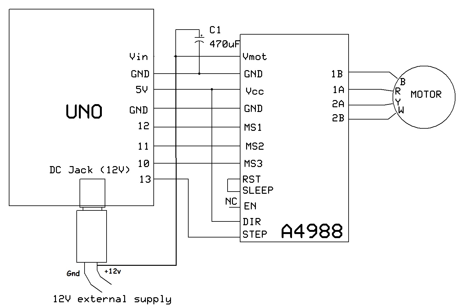
Can you please post a schematic of your project?
What is your power supply?
I agree with what has been said, direct drive platters are very expensive and unless you put a record and pickup on and test the audio, you will not know if your project is a success.
Hi,
So you are using the Vin pin to supply the motor with 12V from the DC jack.
I would advise you connect the Vmot terminal of the A4988 directly to the 12V supply .
You are at the moment running current through a protection diode on the UNO board and its PCB tracks that may not be able to handle the stepper motor current.