i was using driver A4988 when using it the stepper motor(neema 17) was not turning with no vibration and also when checking the current with multimeter it was 120 mA and on the another driver it was zero mA between motor and driver but there was severe heating . Are there any suggestion on how to check whether it was working or not .. or am i doing anything wrong ?
That's a clear sign of some kind of failure.
Please post a schematic of your project and a clear photograph of how you have everything connected together.
Did this stepper driver work well, previously, or has it been malfunctioning right from the start?
Sounds like a wiring error, and possibly, destroyed motor driver. Loose connections and/or changing wiring while powered up can lead to instant destruction.
the stepper motor(neema 17)
Please post links to the stepper motor, the stepper driver and power supply, a wiring diagram, and explain how you set the current limit.
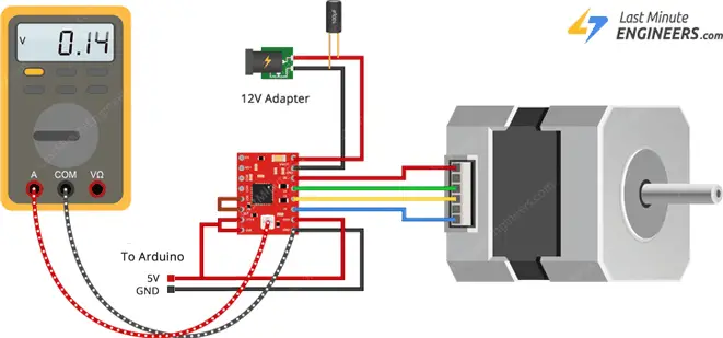
this is the website i referred
it worked fine at first
i checked the rating in the datasheet then connected the driver to stepper motor and driver to arduino nano board where logic 5 volt is given to step, dir , Vdd .
at first checked the current from driver to motor then adjusted the potentiometer to the rated value.
Be aware that the A4988 is good for 1A coil current without a heat sink. With active cooling and a heat sink the A4988 can go to 1.5A.
A data sheet for the stepper motor would also be helpful.
Format your test code using the IDE autoformat tool then post the code as described by the how to get the most from the forum posts.
It is imperative that the coil current limits on the stepper driver be properly set before the motor is used. Did you do that?
i don't know but Sir can you explain the process ? to check whether i did it not
Please supply the requested information.

Hi, @haribeginner
Welcome to the forum.
Can you please post a link to data/specs of your stepper motor.
Can you please post a copy of your circuit, a picture of a hand drawn circuit in jpg, png?
Hand drawn and photographed is perfectly acceptable.
Please include ALL hardware, power supplies, component names and pin labels.
Can you please post a picture of your project?
So we can see your component layout.
Thanks.. Tom... ![]()
![]()
![]()
![]()
it is Nema 17 stepper motor one of them is model 17HS4401S
Nema17 Bipolar.
Brief Data:
• Number of Phase: 2.
• Step Angle: 1.8°.
• Phase Voltage: 2.6Vdc.
• Phase Current: 1.7A.
• Resistance/Phase: 1.5Ω ±10%.
• Inductance: 2.8mH ±20% (1KHz).
• Number of Wire: 4 (100cm Length).
• Holding Torque: 43Ncm.
• Shaft Diameter: Ø5mm.
• Motor Length: 40mm.
• Rotor Inertia: 54gcm2
.
• Temperature rise: 80°C Max.
• Insulation Class: B.
• Dielectric Strength: 500VAC/1-minute.
• Mass: 280g.
and another motor model is 42HD4027-01
● Name: 42 Stepper Motor
● Size:424240mm
● Model:42HD4027-01
● Weight:275g/pc
● Length:40mm
● Port of wires:6 pins female PH2.0
● Number of phase:2
● Step Angle:1.8°
● Holding Torque:400mN.m
● Rated voltage:3.3V
● Rated current:1.5A
● Insulation class:Class B (130°)
● Inductance per phase:3.8mH±20%
● Resistance per phase:2.2Ω±10%
supply given to motor is 12 volts but at that time it is 10.95 volts
a capacitor is fixed across the battery to prevent spikes

Referring to picture in post #10, if you switched the meter range while the driver was powered, you may have ruined the A4988.
i just changed the meter while it was powered up
that was cause of ruin
Hi, @haribeginner
Please post your code, in case you have some simple programming errors.
Otherwise, can I suggest that you forget your code for the moment.
Setup your controller and stepper driver and motor ONLY.
Then write code to get the stepper moving.
Lets establish that you can control the steppers before adding anything else.
Its called programming in stages and can save many, many hours of frustration.
What Arduino controller are you using?
Tom... ![]()
![]()
![]()
![]()
arduino nano here is the code
// Define pin connections & motor's steps per revolution
const int dirPin = 2;
const int stepPin = 3;
const int stepsPerRevolution = 200;

void setup()
{
	// Declare pins as Outputs
	pinMode(stepPin, OUTPUT);
	pinMode(dirPin, OUTPUT);
}
void loop()
{
	// Set motor direction clockwise
	digitalWrite(dirPin, HIGH);

	// Spin motor slowly
	for(int x = 0; x < stepsPerRevolution; x++)
	{
		digitalWrite(stepPin, HIGH);
		delayMicroseconds(2000);
		digitalWrite(stepPin, LOW);
		delayMicroseconds(2000);
	}
	delay(1000); // Wait a second

	// Set motor direction counterclockwise
	digitalWrite(dirPin, LOW);

	// Spin motor quickly
	for(int x = 0; x < stepsPerRevolution; x++)
	{
		digitalWrite(stepPin, HIGH);
		delayMicroseconds(1000);
		digitalWrite(stepPin, LOW);
		delayMicroseconds(1000);
	}
	delay(1000); // Wait a second
}
Please state how you set the A4988 current limit to 1 Ampere or less.
Please post a photo of the setup, showing the connections between the motor, motor power supply and the driver.
i have posted above refer post 9
Did you set the pot so the meter read 1.00 Amps? That should be done with the motor disconnected and voltage read at the Vref test point.
i did it without disconnecting is that where the damage occured ?