
Beefy99:
Is the following diagram effectively GND?
I still don't see any GND connection between the Arduino and the A4988.
A photo of a simple pencil drawing of your connections would be much easier to make sense of than a Frtizing picture.
I don't know why my program is not working for you as you have not posted the exact code you uploaded to your Arduino.
...R
Hi,
I have just wired my step and direction pins to 8/9 and uploaded your first sketch and the motor ran in one direction,which is correct.
After I wired in switch pins to 10/11 and then uploaded your second sketch and the motor ran in one direction without pressing any buttons. Then I press one button which had no effect,the motor continued to run same direction and speed. The other button when pressed made the motor change direction and when released the motor reverted back to the original direction.
code I used
byte directionPin = 9;
byte stepPin = 8;

byte buttonCWpin = 10;
byte buttonCCWpin = 11;

boolean buttonCWpressed = false;
boolean buttonCCWpressed = false;

byte ledPin = 13;

unsigned long curMillis;
unsigned long prevStepMillis = 0;
unsigned long millisBetweenSteps = 25; // milliseconds

void setup() {

  Serial.begin(9600);
  Serial.println("Starting Stepper Demo with millis()");

  pinMode(directionPin, OUTPUT);
  pinMode(stepPin, OUTPUT);
  pinMode(ledPin, OUTPUT);

  pinMode(buttonCWpin, INPUT_PULLUP);
  pinMode(buttonCCWpin, INPUT_PULLUP);

}

void loop() {

 curMillis = millis();
 readButtons();
 actOnButtons();

}

void readButtons() {

 buttonCCWpressed = false;
 buttonCWpressed = false;

 if (digitalRead(buttonCWpin) == LOW) {
 buttonCWpressed = true;
 }
 if (digitalRead(buttonCCWpin) == LOW) {
 buttonCCWpressed = true;
 }
}

void actOnButtons() {
 if (buttonCWpressed == true) {
 digitalWrite(directionPin, LOW);
 singleStep();
 }
 if (buttonCCWpressed == true) {
 digitalWrite(directionPin, HIGH);
 singleStep();
 }
}

void singleStep() {
 if (curMillis - prevStepMillis >= millisBetweenSteps) {
 prevStepMillis += millisBetweenSteps;
 digitalWrite(stepPin, HIGH);
 digitalWrite(stepPin, LOW);
 }
}
Im not sure why it wont run like you describe,any ideas???
Cheers.
Hi,
Can you post a picture of your project so we can see your layout, please?
Thanks... Tom.. ![]()
Beefy99:
After I wired in switch pins to 10/11 and then uploaded your second sketch and the motor ran in one direction without pressing any buttons.
I wonder if the switches are wired incorrectly?
Put in some Serial.print() commands so you can see what the buttons are doing.
...R
Hi,
Do you have a DMM to measure some voltages around your project?
Tom... ![]()
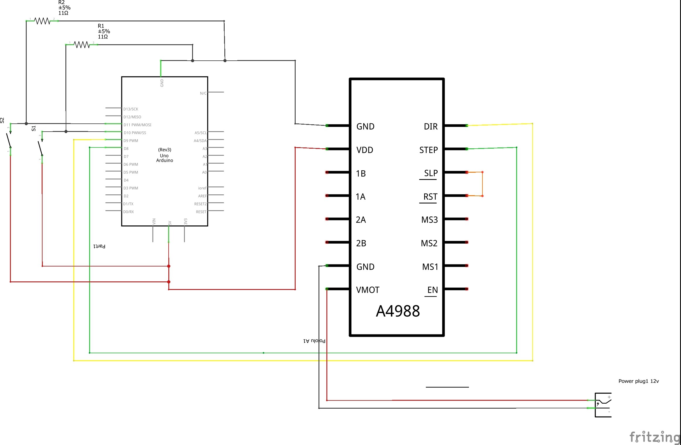
I can't read the left hand part of the image even when I enlarge my screen.
With a simple pencil drawing there is no difficulty ensuring that all the relevant items can be read.
But if you insist on using your PC to make the drawing then have a look at the images in this Simple nRF24L01+ Tutorial that I created with LibreOffice Draw. You could the same thing with any drawing program.
...R

If those resistors are 11 ohms that is much too low and will overload the Arduino I/O pins. Try 4700 ohms - you don't need much current for a switch. Better still use pinMode(pin, INPUT_PULLUP) and you won't need any external resistor.
...R
Hi,
I think they are 22k as the color code is red red orange gold.
Is this correct?
Beefy99:
I think they are 22k as the color code is red red orange gold.
Shoot - there was me thinking you had prepared the drawing carefully ![]()
...R
At 11 ohms those resistors are stupidly small. They should be three orders of magnitude higher.
Grumpy_Mike:
At 11 ohms those resistors are stupidly small. They should be three orders of magnitude higher.
Now two of us have wasted time on that issue ![]()
According to Reply #32 they are really 22k
...R
LOL
Beefy99:
LOL
Ok funny that you don't appreciate help. Remembering that.