Right now I'm trying to make one motor on the Y axis to spin in both directions. But for some reason it rotates in the same direction no matter which pulses I send
here's the code:
const int stepPin = 3;
const int dirPin = 6;
const int enPin = 8;

void setup()
{
  Serial.begin(115200);
  pinMode(stepPin, OUTPUT);
  pinMode(dirPin, OUTPUT);
  pinMode(enPin, OUTPUT);
  digitalWrite(enPin, LOW);
}

void loop()
{
  digitalWrite(dirPin, HIGH); // Enables the motor to move in a particular direction
  Serial.println("direction pin HIGH");
  for (int x = 0; x < 100; x++)
  {
    digitalWrite(stepPin, HIGH);
    delay(50);
    digitalWrite(stepPin, LOW);
    delay(50);
    Serial.print("Step number ");
    Serial.println(x);
  }
  delay(2000); // One second delay
  digitalWrite(dirPin, LOW); //Changes the direction of rotation
  Serial.println("direction pin LOW");
  for (int x = 0; x < 100; x++)
  {
    digitalWrite(stepPin, HIGH);
    delay(50);
    digitalWrite(stepPin, LOW);
    delay(50);
    Serial.print("Step number ");
    Serial.println(x);
  }
  delay(1000);
}
Is there a specific value Vref needs to show? I twisted it in both directions and stopped it when the motor seemed to work smoothly(still only in one direction though)
Here's a diagram of the board (the only things connected to the shield are the motor and a psu)
I also wonder how microstepping works. The pinouts on the internet for M0, M1 and M2 (2, 3 and 4) overlap with step and dir pins for the axes(2-7), how can that work?
And also my X axis sockets are broken. I'm making a pen plotter, can I just set Z axis pins as the X axis in the code? I need the Z axis to control the servo through Inkscape to pull the pen up and down
Here it is!
I tried the wiring from the motor's description and every possible way of wiring it and it didnt work, this specific one, though (1B on the motor to 2B on the shield, 1A to 1A, 2A to 2A, 1B to 2B), does work semi-correctly
Yes I had that problem for a long time because the motors are cheap, so the wires were jumbled up! I had to try every single possible configuration before I found the one I have now - it finally spins, but only in one direction
Very important connect / disconnect stepper-motor only if powersupply is switched OFF.
Stepper-motors have coils. Coils can produce high voltage-spikes when you connect or disconnect a coil from the power-supply. A single voltage-spike can destroy the stepper-motor-driver.
So make sure that you have switched off your power-supply before you connect / disconnect steppermotor-wires.
Do never play or change the stepper-motorwires while powersupply is switched on.
Make sure that your stepper-motor-wires have a real tight connection so they will not loose contact.
If you want really help you will have to provide a schematic of the motorshield
Do you have a digital multimeter?
If you haven't a schematic of exact that motorshield you should analyse which IO-pin is connected to what yourself.
Switch off power. Unplug the stepper-motordrivers
Set the digital multimeter to continuity test.
Connect one test lead to the pin connecting the motor shield to the Arduino which you use as the DIR-output.
Connect the other test lead to the connector labeled DIR on the stepper motor driver.
Does the digital multmeter beep to indicate that there is connection?
repeat this procedure to find out which female socket of the stepper-motordriver-socket is connected to what male pin that connects to the arduino uno
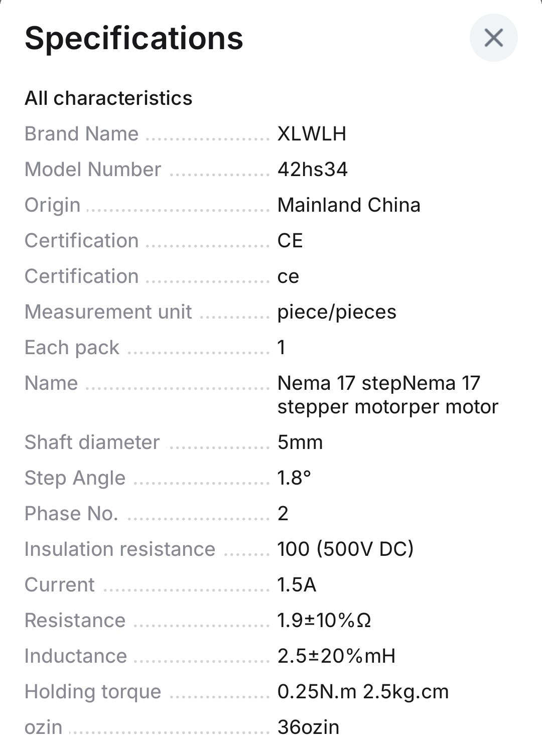
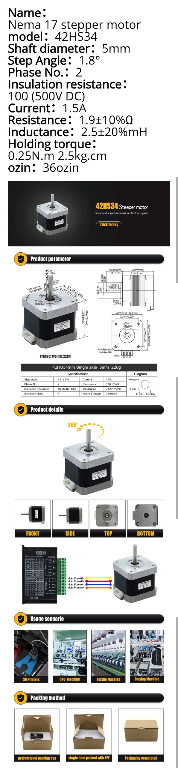
What exact type of stepper-motor is this. Does the stepper-motor have a nameplate with some numbers on it?
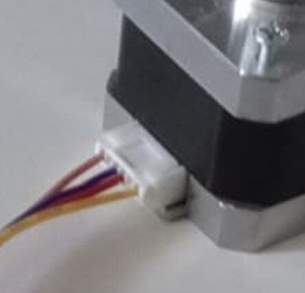
Seems to have 6 contacts but only 4 of them have wires.
It might be that this is a unipolar stepper-motor which needs a different wiring than a bipolar steppermotor.
If you have powersupply switched of and you unplug the connector from the stepper-motor how many male pins are on the stepper-motor?
...says red&yellow on 4&6 is one coil, and orange&blue on 1&3 is the other. Seems like it might be OK from the #5 pic.
Maybe there's no continuity on the shield between the Arduino pin 6 and the DIR pin on the driver?
I'd try moving the other driver board to the X or Z socket and changing the pin numbers appropriately and using it. You could leave it in the A socket, but then there's some jumper trickery that needs to be correct.
My jumpers are relatively loosely connected to the driver pins, and I can remember at least 2 times when they disconnected. Before any of them, when I just got the motors, I used code for a unipolar driver and it erratically rotated in two directions. A month later I got them to rotate again with proper code
I really hope I didn't fry my motors....
But they shouldn't be fried, because when I used this code:
// defines pins numbers
const int stepX = 2;
const int dirX  = 5;
const int stepY = 3;
const int dirY  = 6;
const int stepZ = 4;
const int dirZ  = 7;
const int enPin = 8;

void setup() {
 // Sets the two pins as Outputs
  pinMode(stepX,OUTPUT);
  pinMode(dirX,OUTPUT);
  pinMode(stepY,OUTPUT);
  pinMode(dirY,OUTPUT);
  pinMode(stepZ,OUTPUT);
  pinMode(dirZ,OUTPUT);
  pinMode(enPin,OUTPUT);
  digitalWrite(enPin,LOW);
  digitalWrite(dirX,HIGH);
  digitalWrite(dirY,LOW);
  digitalWrite(dirZ,HIGH);
}

void loop() {
  // Enables the motor to move in a particular direction
  // Makes 200 pulses for making one full cycle rotation
  for(int x = 0; x < 800; x++) {
    digitalWrite(stepX,HIGH);
    delayMicroseconds(1000);
    digitalWrite(stepX,LOW);
    delayMicroseconds(1000);
  }
  delay(1000); // One second delay

   for(int x = 0; x < 800; x++) {
    digitalWrite(stepY,HIGH);
    delayMicroseconds(1000);
    digitalWrite(stepY,LOW);
    delayMicroseconds(1000);
  }
   delay(1000); // One second delay

  for(int x = 0; x < 800; x++) {
    digitalWrite(stepZ,HIGH);
    delayMicroseconds(1000);
    digitalWrite(stepZ,LOW);
    delayMicroseconds(1000);
  }
   delay(1000); // One second delay
}
The motor was jerking back and forth in both directions, so there's a chance they aren't fried and they are bipolar for sure
I don't have the shield's or arduino's exact model as the seller's page is gone, but the exact model of the motor is this XY42HS34 19V:
Ah, that's a huge relief, I have spare drivers to replace the old ones.
I'll wait until I get a multimeter to be 100% sure I wired the polarity correctly and then run the same code with a new driver and post the results