The issue I'm encountering is the following:
I have 3 steppers (17HE19-2004S, datasheet can be found here https://www.omc-stepperonline.com/index.php?route=product/product/get_file&file=2731/17HE19-2004S.pdf) wired to DRV8825 on my CNC shield, and when I send what I assume to be correct code on the arduino (validated by user groundfungus on a similar setup) it doesn't work as expected. Motors make weird noises at the beginning, then make regular ticking sounds "forever" (until you stop the arduino), but they don't move. They are powered since the shaft is stiff ie you can't rotate it with your fingers.
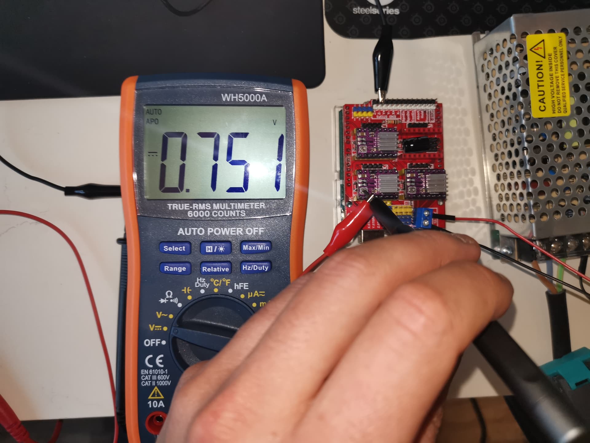
I setup Vref to 0.75V since the current per coil of my motor is 2A at max.
Here is the code tried:
#include <MobaTools.h>
const int stepsPerRevolution = 200;                 // number of steps per revolution of the steppers used
MoToStepper MotorX(stepsPerRevolution, STEPDIR);    // create one bipolar stepper using stepper mode, since motor is connected via DRV8825, with 200 steps per revolution
MoToStepper MotorY(stepsPerRevolution, STEPDIR);    // Idem
MoToStepper MotorZ(stepsPerRevolution, STEPDIR);    // Idem
//int limitSwitchY = 10;                              // To later on allocate pin 10 to the limit switch associated with MotorY
//int limitSwitchZ = 11;                              // To later on allocate pin 11 to the limit switch associated with MotorY

void setup() {
  // ----Constants----
  MotorX.attach(2,5);                              // STEPpin, DIRpin arccording to CNC shield routing
  MotorY.attach(3,6);                              // Idem
  MotorZ.attach(4,7);                              // Idem
  MotorX.setSpeed(600);                            // Set rotation speed of motor X to 60 rpm
  MotorX.setRampLen(50);                           // Set 50 steps acceleration ramp for MotorX
  MotorY.setSpeed(600);                            // Set rotation speed of motor Y to 60 rpm
  MotorY.setRampLen(50);                           // Set 50 steps acceleration ramp for MotorY
  MotorZ.setSpeed(600);                            // Set rotation speed of motor Z to 60 rpm
  MotorZ.setRampLen(50);                           // Set 50 steps acceleration ramp for MotorZ
  //pinMode(limitSwitchY, INPUT);                   // Set input sense for limitSwitchY (pin 10)
  //pinMode(limitSwitchZ, INPUT);                   // Set input sense for limitSwitchZ (pin 11)

  // ----Initialization actions----
  MotorX.rotate(1);                                // MotorX starts to rotate forward continuously
}

void loop() {
  // put your main code here, to run repeatedly:
  MotorY.write(360);
  MotorZ.write(-360);
}
I tried with another stepper lib: accelstepper. I had the same results.
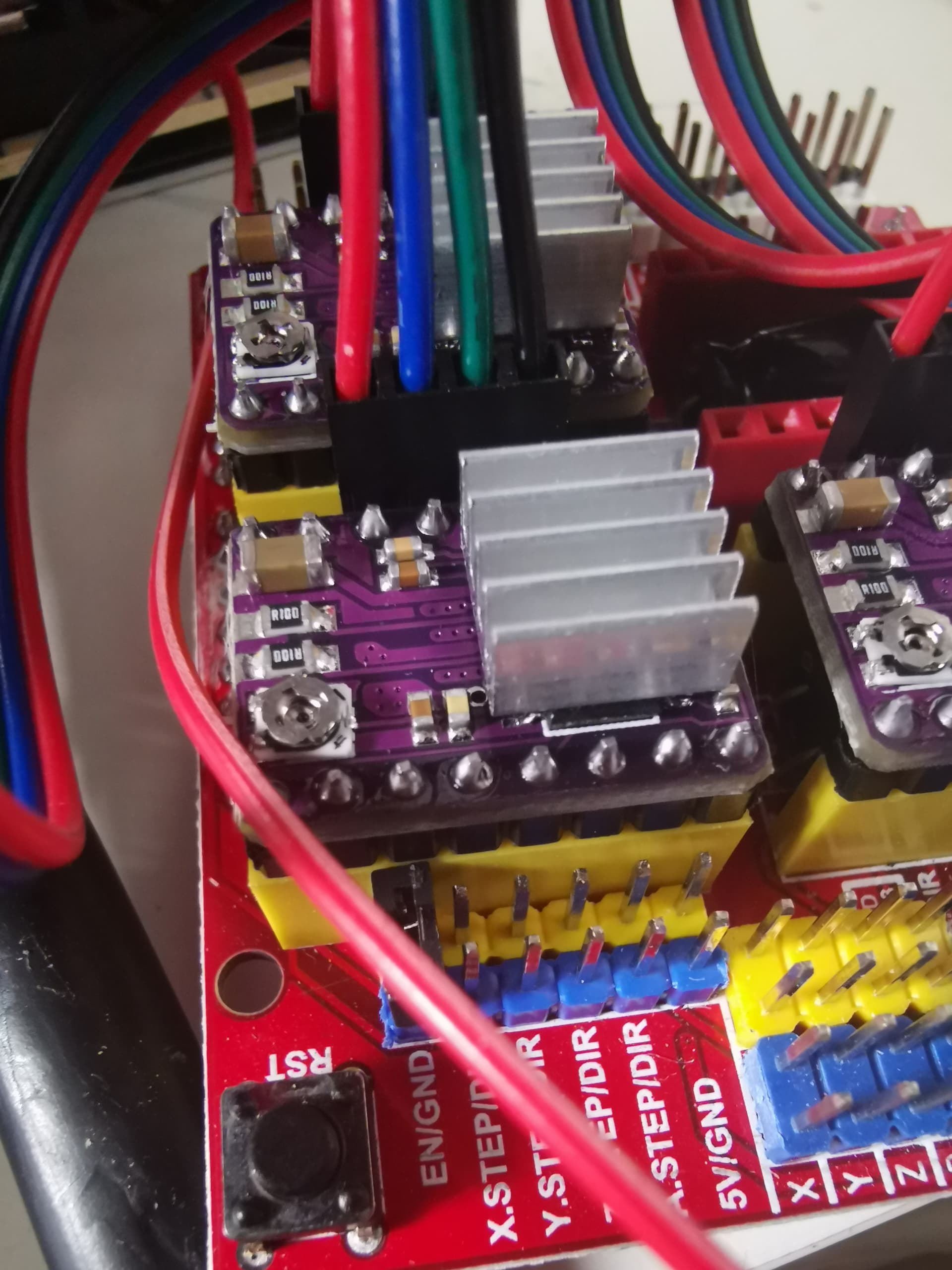
Here is a picture of my setup:
So issue could come from:
a. the drivers (but it's not very probable the 3 of them have an issue)
b. the power supply (it is 12V 8.3A, maybe I need a 24V?)
c. the CNC shield
d. the arduino
e. Incorrect wiring
To move on, I ordered some spare CNC shield and drivers that are on their way, but in the meantime what can I do to investigate further? Where to start?
That tells nothing without having the datasheet of the drivers and knowing the current measuring resistor value. They differ from board to board.
The datasheet of the power supply, please.
Due to the nature of Your issue, schematics please.
Hello, thanks for your answer. Sorry but having limited knowledge in electronics, I'll try my best to answer but I could have misinterpreted something.
Sure but there are plenty of different versions there.
You will not get the resolving answer by avoiding precise answers, duck instead of facing the questions.
Helping members to get the question in order is frustrating and happening too often.
Usually if the motor didn't run but with sounds and ticking is due to : 1. Wrong frequency to drive, 2. No sufficent current, 3. Wrong wired.
From your attached photos, it looks wired incorrectly. I have the similar motors with 6 pins. 1.2.3.4.5.6. it can be used as bipolar (4 pins 1,3,4,6 as CNC shield needed) or unipolar (6 pins).
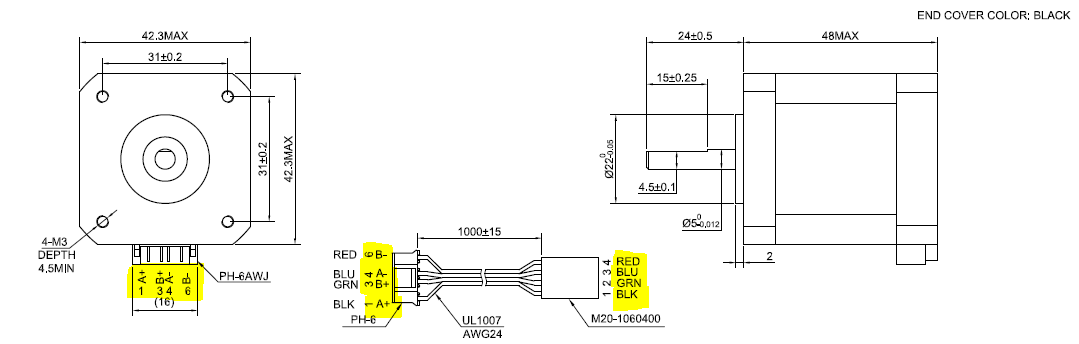
There are 2 wiring groups of this kind of motors : 1,2,4 and 3,5,6 In your pictures, your connection to CNC shield is 1(Black)-3(Green) to A drive, and 4(Blue)-6(RED) to B drive .
That is to change the same wiring (1-4) to A drive and (3-6) to B drive . Please swap one side of pin connect ( Black-Green-Blue-Red ==> Black-Blue-Green-Red)
Before you do this, can double confirm by checking the wiring with Ohm meter, see if the motors wiring are 1,2,4 and 3,5,6. Same wiring has very low resistance ( <10 ohm, depends on motor), different wiring has high resistance.
OK, having no experience in electronics other than what I've been taught in high school, I thought the info on the page provided was pretty well made and sufficient. This not being the case, here is the datasheet of the controller on the pololu card (violet board on the picture above): drv8825.pdf (1,7 Mo)
Regarding the pololu card itself, it seems there is no available datasheet other than what can be found on the website. If I'm mistaking, please feel free to say so.
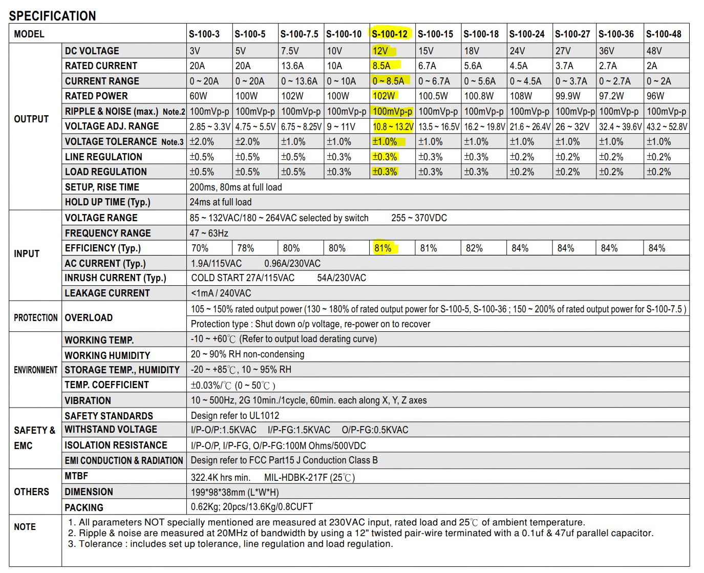
Sorry maybe I misunderstood your comment, but it is the S-100-12 ie the one I highlighted in below screencap:
Note that it is not the one from the meanwell brand though, it's a cheap power supply bought on aliexpress. I can't find any datasheet on the seller page. On the labelling, the ref is S-100-12 though, that's why I provided a reference to the meanwell products datasheet.
That is not what I am doing. As said above, having no experience, I do or provide what I think is the most appropried thing in order to ease the support process, but it might not be what is really needed. In that case, please feel free to say so and to precise what you expect in terms of info or content, and I'll do my best to go further or dig.
That being said, I appreciate the fact you and other members take some time to support beginner hobbyists like me to get what they expect from the arduino.
I double checked with my Ohm meter, and confirmed that low resistance is between pins [1 - 4] and [3 - 6], which confirms the statements above.
Then about the order of the wires on the CNC shield, I tried to check on the CNC shield schematic. Which didn't help so I don't report it in here.
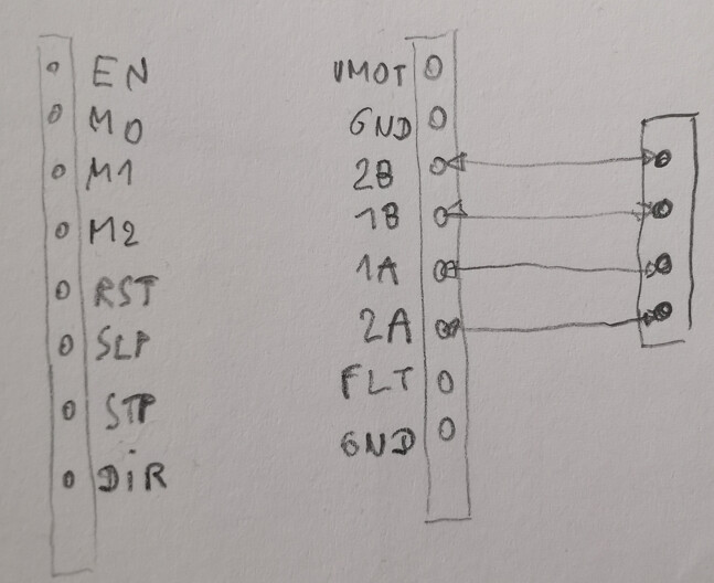
Then I checked the pinout of the pololu driver board, and verified with the Ohm meter how it is mapped with the 4 pins next to the driver on the CNC shield.
The connectors in question:
The mapping (pretty straightforward but a surprise happens more often than we think):
The reason why I found this : I just bought few more 42 motors. It has similar 6 pins. When I connect them to my driver circuit, I found the pins connect the 2 wiring in 1-2-4 and 3-5-6. I am not quite understand why it is not 1-2-3 and 4-5-6 which is more straight forward . And you don't need to swap the pins when connecting to the driver circuits.
Motor 28BYP-48 also like this (It work as unipolar, so not an issue.) But can be used as bipolar, then need to watch the pin connections.
Yes this is kind of strange... Also, the cables were provided with the motor, so I didn't even think it would not be plug & play.
In the end what I did is I swapped the blue and green wires in the dupont connector on the board side. You just have to remove the tiny plastic clips that retain the wires, and change the order.
Thanks again for your help.