STM32 w/FTDI - Uploads but won't run

I have 2 blue pill clones. The one I'm using was working just fine a couple of weeks ago (I went out of town, came back yesterday), but now it won't even run the blink program and I can't figure out what's happened. I've gone through a bunch of posts here and on other sites and can't seem to narrow it down to anything.

I haven't changed any settings in the Arduino IDE, nor have I touched the breadboard that has the Arduino seated and wired up. I've checked that all the jumpers are connected properly a few times.

I have the FTDI board with the voltage jumper set to 5V and it powers the Arduino via the 5V and GND pins. TX goes to A10, RX goes to A9. I have BOOT0 set HI and BOOT1 set LOW

In the output window, I get:

      -------------------------------------------------------------------
                       STM32CubeProgrammer v2.11.0                  
      -------------------------------------------------------------------

Serial Port COM8 is successfully opened.
Port configuration: parity = even, baudrate = 115200, data-bit = 8,
                     stop-bit = 1.0, flow-control = off
Activating device: OK
Board       : --
Chip ID: 0x410 
BootLoader protocol version: 2.2
Device name : STM32F101/F102/F103 Medium-density
Flash size  : 128 KBytes (default)
Device type : MCU
Revision ID : --  
Device CPU  : Cortex-M3


Memory Programming ...
Opening and parsing file: Blink.ino.bin
  File          : Blink.ino.bin
  Size          : 10.63 KB 
  Address       : 0x08000000 


Erasing memory corresponding to segment 0:
Erasing internal memory sectors [0 10]
Download in Progress:


File download complete
Time elapsed during download operation: 00:00:02.774

RUNNING Program ... 
  Address:      : 0x8000000
Start operation achieved successfully

I have not changed any of the settings for the

If I add serial logging, nothing gets logged to the serial port.

Does anyone have any ideas for what I might be wrong?

These are front and back pictures of one of the 2 boards I have (in case they help identify the specific variation of clone I have). They both have the white stuff on the bottom of the boards. It's under the jumpers for BOOT0 and BOOT1 and under the crystal. Never noticed it before, but I never really looked.


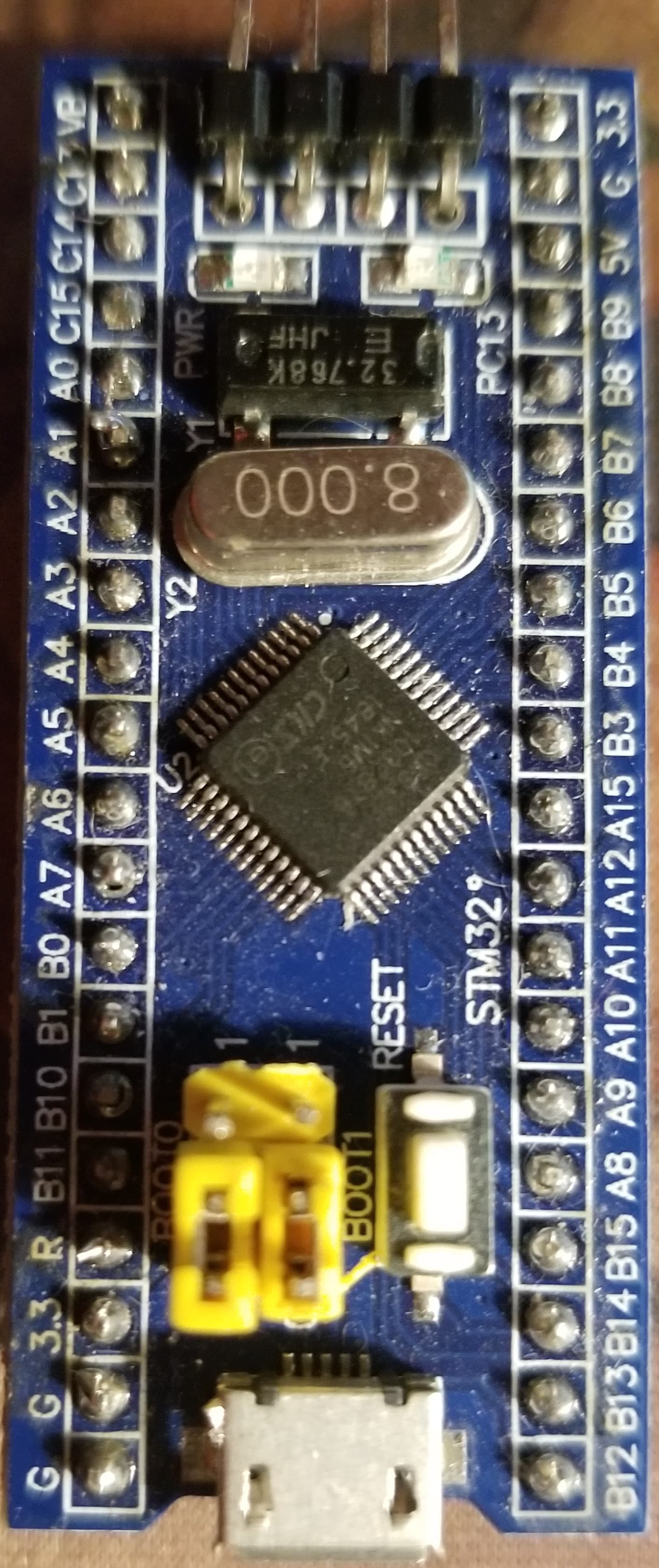
(yes, in the photo BOOT0 was LOW, but it wasn't when I was programming it)

I've tried replacing one Blue Pill with the other and same results. I really appreciate any help anyone can offer.

In a situation like this posting schematics is mandatory. Don't post Fritzings. Links to datasheets of the FTDI can help. Not every helper has such a one in the draver.

What is a "Fritzing"?

Schematic of what? The FTDI board is connected to the blue pill as I specified, with 4 wires. The FTDI board is just the standard red FTDI board you see in every mockup of a blue pill. I don't know what model number it is. It just says FTDI232 on the back. Mine is set up exactly as shown here.

Or as this diagram from the page shows:

What blink program are you uploading? Can you please post it?

Sure. It's just the built-in sample sketch. I use it to test if I have things connected properly, when hooking up a new board.

/*
  Blink

  Turns an LED on for one second, then off for one second, repeatedly.

  Most Arduinos have an on-board LED you can control. On the UNO, MEGA and ZERO
  it is attached to digital pin 13, on MKR1000 on pin 6. LED_BUILTIN is set to
  the correct LED pin independent of which board is used.
  If you want to know what pin the on-board LED is connected to on your Arduino
  model, check the Technical Specs of your board at:
  https://www.arduino.cc/en/Main/Products

  modified 8 May 2014
  by Scott Fitzgerald
  modified 2 Sep 2016
  by Arturo Guadalupi
  modified 8 Sep 2016
  by Colby Newman

  This example code is in the public domain.

  https://www.arduino.cc/en/Tutorial/BuiltInExamples/Blink
*/

// the setup function runs once when you press reset or power the board
void setup() {
  // initialize digital pin LED_BUILTIN as an output.
  pinMode(LED_BUILTIN, OUTPUT);
}

// the loop function runs over and over again forever
void loop() {
  digitalWrite(LED_BUILTIN, HIGH);   // turn the LED on (HIGH is the voltage level)
  delay(1000);                       // wait for a second
  digitalWrite(LED_BUILTIN, LOW);    // turn the LED off by making the voltage LOW
  delay(1000);                       // wait for a second
}

You may have to override LED_BUILTIN and provide the pin number.

I've used this board a number of times and I've used this same blink sample to test if I have it hooked up properly. I've never had to modify it in the past.

Did you reset the board after uploading? Also, are you sure the jumpers are right for post-upload operation?

Just what You posted. They are usually useless. The same for this one. It has no powering and is stone dead. Powering failures are as common as sun and rain.

I don't know what you mean by this. Both boards have red power indicator LEDS indicating that they are powered. When I upload the sketch, the green LED on the FTDI board blinks during the comms, indicating that the USB communications are working.

As for the fritzing, I'm not entirely sure what I can provide in a schematic that it doesn't provide. I have the USB connected to the FTDI board. The FTDI board is connected to the blue pill as I've described and shown in the fritzing. What is a schematic going to show that isn't communicated. I ask in all seriousness. I'm very confused by what part of this isn't clear to you.

Let's just focus on the problem. Is any hardware attached to the board other than the FTDI? What version IDE are you using?

I've tried resetting. No effect. I don't normally have to change the jumpers. I just click the Upload button and the sketch uploads and begins running immediately.

If I disconnect and reconnect, then I have to switch the jumper or it will erase the sketch.

I disconnected everything else, except the FTDI to blue pill wires when I couldn't get it working, to rule out any other issues.

I've never heard of this one before! Are you sure? AFAIK, you have to perform programming to erase anything.

I'm not sure it erases it, but if I disconnect and reconnect, it no longer runs the sketch. If I disconnect, move BOOT0 to LOW, then it will run the sketch. Perhaps it's not erasing the sketch, maybe it's just not running it right away. Sorry, that was just an assumption on my part.

Here's what it looks like

You are programming with BOOT0==HIGH and then changing BOOT0==LOW to run, right?

You are using this tutorial?
https://www.electronicshub.org/getting-started-with-stm32f103c8t6-blue-pill/

Are you sure your FTDI is a 5V device? It comes in that, or 3.3V. There is often a voltage selection jumper on the back. Did the same FTDI work previously, or is this a different one? Have you tested it by looping back the serial with a wire jumper?

I got it working. I started trying different boards in the Board Part Number selection. "Blue Pill F103CB (or C8 with 128k)" seems to work. But I haven't changed it since I used it before I left town. So I don't know why it used to work under the "Generic F108C8Tx" and now it won't. I have the setting in my notes as well, as what I've used in the past. So very strange. In fact, I've specifically tried the Blue Pill board options (there are only 2) and they didn't work, which is how I ended up on the Generic...

Thanks for all the help. I learned several things I didn't know, so I appreciate it.

The STM programming interface is a lot more trouble, but you have to do it if you want to use the chips. I also have struggled with similar issues. But it's usually possible to succeed with patience. Happy coding.

1 Like

Please communicate via schematics, diagrams, datasheet links as a beginning. Words are way too often confusing. "I connected this wire here and there" and things like that are common. In the end the wrong voltage connected for powering is often the reason, or batteries not having the needed capacity. Analyzing "novells" forces helpers to bring up pen and paper trying to get the overview. Sending You guesses wastes Your and helpers time.
Hopefully other participating helpers will crack the nut.

1 Like

See, LED_BUILTIN can't mean anything for a Generic board...

I was not aware of that. But like I said, even serial logging wasn't working, regardless of the blinking. I should have been able to see the log messages I added. I could see them once I changed the board selection.