Hello all,
I am quite new to arduino so this might a very simplistic, or maybe not..., either way i am not going to have much hair left in a weeks time.
Firstly what it does/should do.
The concept is to measure the duration of a squarewave and based on the length (1 sec, 3 sec, 5 sec,7 sec) activate a solenoid via n-ch mosfet. I have done this via interrupts looking for the rising edge (start timer) then falling edge (stop the timer). Everything working perfectly.
The problem came when i encountered a grounding problem and had to make a dc-dc converter. In short, I just made a 'dirty' quick fix, using another n-ch mosfet to do the switching for me(again this works fine on its own). Then assigned a pwm to take care of that, when i did this however i screwed up my first part of the program. Once i take out the pwm it works fine again... where is the problem???
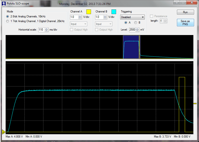
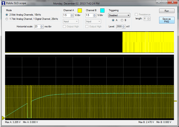
Its doesnt appear to be the hardware. I checked the PWM it seems fine, i can upload o-scope pictures.
IF this helps, i noticed that if i enable my pwm but just don't connect that pin to anything else (o-scope, mosfet) it works fine but then obviously the dc-dc converter does work.
I am using an Arduino Uno R3.
PWM is connected on pin 11 (using timer 2
solenoid outputs are 4-7
interrupts on pins 2,3.
My main code is as follows
#include <StopWatch.h>

StopWatch SW;

int PWMPin = 11;
void setup() {
          // initialize required digital pins as an output / input

          pinMode(13, OUTPUT); // LED response - onboard arduino

          //pinMode(11,OUTPUT);
          //analogWrite(PWMPin, 127); // PWM for DC - DC converter

          attachInterrupt(1, Timer_start, RISING);
          attachInterrupt(0, Phone_Signal, FALLING);
          // enables interrupt on 'int0' (PIN 2 & 3 on dev board) & sets the interrupts to trigger on a rising and falling input

          //Assigning pins to be output to solenoids
          pinMode(4, OUTPUT);
          pinMode(5, OUTPUT);
          pinMode(6, OUTPUT);
          pinMode(7, OUTPUT);

}

void loop()
{

}
void Timer_start() // starts the timer
{
                 SW.reset();	// resets the measurement
                 SW.start();	// start / continue the measurement
}

void Phone_Signal()
{
              SW.stop();	// stops the measurement

                             if (SW.value() < 1500 && SW.value() > 50) //i want 1000 mS just giving it alot of room (pulse is 1 sec exactly)
                                {
                                  digitalWrite(4,HIGH);
                                  delay(500);
                                  digitalWrite(4,LOW);
                                }
                      else if (SW.value() < 4000 && SW.value() > 1500) //i want 3000 mS just giving it alot of room (pulse is 3 sec exactly)
                                 {
                                   digitalWrite(5,HIGH);
                                   delay(500);
                                   digitalWrite(5,LOW);
                                 }

                       else if (SW.value() < 5100 && SW.value() > 4000)//i want 5000 mS just giving it alot of room (pulse is 5 sec exactly)
                                 {
                                   digitalWrite(6,HIGH);
                                   delay(500);
                                   digitalWrite(6,LOW);
                                 }

                        else if (SW.value() < 8000 && SW.value() > 5100)//i want 7000 mS just giving it alot of room (pulse is 7 sec exactly)
                                 {
                                   digitalWrite(7,HIGH);
                                   delay(500);
                                   digitalWrite(7,LOW);
                                 }
                                  else if (SW.value() > 8000 || SW.value() == 0 )//Greater than 8000 mS or timer started but is out of range
                                 {
                                   error();
                                 }
}
void error() // LED is on Constantly if there is an error
{
            digitalWrite(13, HIGH);   // turn the LED on (HIGH is the voltage level)
            delay(50000);
            digitalWrite(13, LOW);
}
I am using the stopwatch library which can be found here
http://playground.arduino.cc/Code/Stopwatch
What am i missing? As far as i can tell the stopwatch is using timer one, whilst the pwm which i am using is using timer 2?
Thanks so much in advance, please let me know if i can provide any additional information
Regards
Chris


