I was hoping someone could give me a little guidance on how to proceed. I have been working on this project for about a month now (in the process wasteing 2 weeks of vaction time) and I can't seem to figure it out. I'm sure it goes without saying this is my first entry into the small electronics world.
I first started trying to get a 4x8 pattern of LEDs to be able to be controlled where every other string of LEDs are controlled separately. So in normal run mode only 4 LEDs are lit up at a time. Using online calculators it seemed like this was far from feasible. I do want the option to turn on all of one color of needed
So now it looks like it can be done with a 3x6 array, However I am exceeding the arduino unos supply. The LEDs spec sheet will be out at the bottom. What I am attempting to do is make the lights flash in a pattern rapidly. Can someone point me in a direction on how to go forward?
bright white LEDs
10,000mcd brightness
Standard size - T1 ¾ 5mm
Forward Voltage:
Min: 3.2V
Max: 3.4V
Max current 20mA
bright yellow LEDs
10,000mcd brightness
Standard size - T1 ¾ 5mm
2.4V forward drop
Max current 20mA
nes999:
I first started trying to get a 4x8 pattern of LEDs to be able to be controlled where every other string of LEDs are controlled separately. So in normal run mode only 4 LEDs are lit up at a time. Using online calculators it seemed like this was far from feasible. I do want the option to turn on all of one color of needed
You should explain a little more clearly. 32 leds white + 32 leds yellow, or a mix? If a mix, how arranged? In what way is it "far from feasable"? How are your "strings" arranged? Can you give us a schematic?
nes999:
So now it looks like it can be done with a 3x6 array, However I am exceeding the arduino unos supply. The LEDs spec sheet will be out at the bottom. What I am attempting to do is make the lights flash in a pattern rapidly.
Why is 3x6 OK but 4x8 was not? Why do you think you are exceeding the uno's supply, and what do you think that is? Don't forget you said that only 4 leds would be lit up at the same time. Could that be any 4 at random, or 4 in a row/column?
Sorry if all I have asked is questions, but your question provided so little unabiguous detail.
PaulRB:
You should explain a little more clearly. 32 leds white + 32 leds yellow, or a mix? If a mix, how arranged? In what way is it "far from feasable"? How are your "strings" arranged? Can you give us a schematic?
Why is 3x6 OK but 4x8 was not? Why do you think you are exceeding the uno's supply, and what do you think that is? Don't forget you said that only 4 leds would be lit up at the same time. Could that be any 4 at random, or 4 in a row/column?
Sorry if all I have asked is questions, but your question provided so little unabiguous detail.
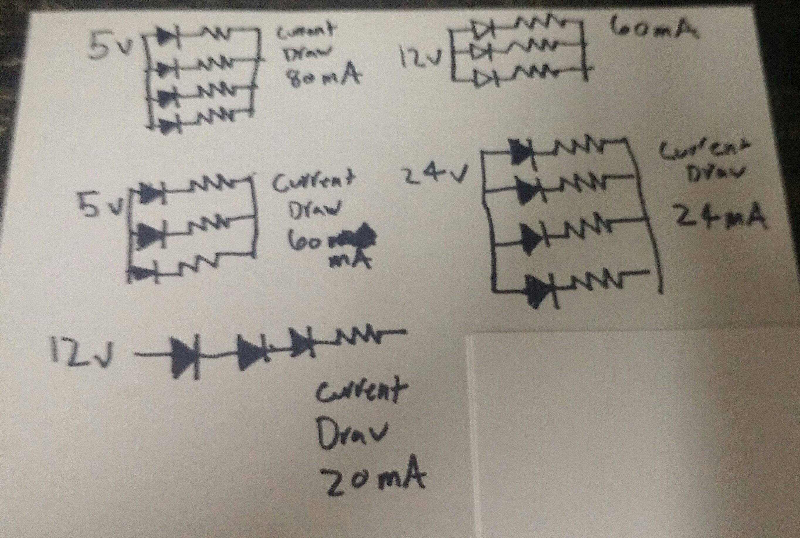
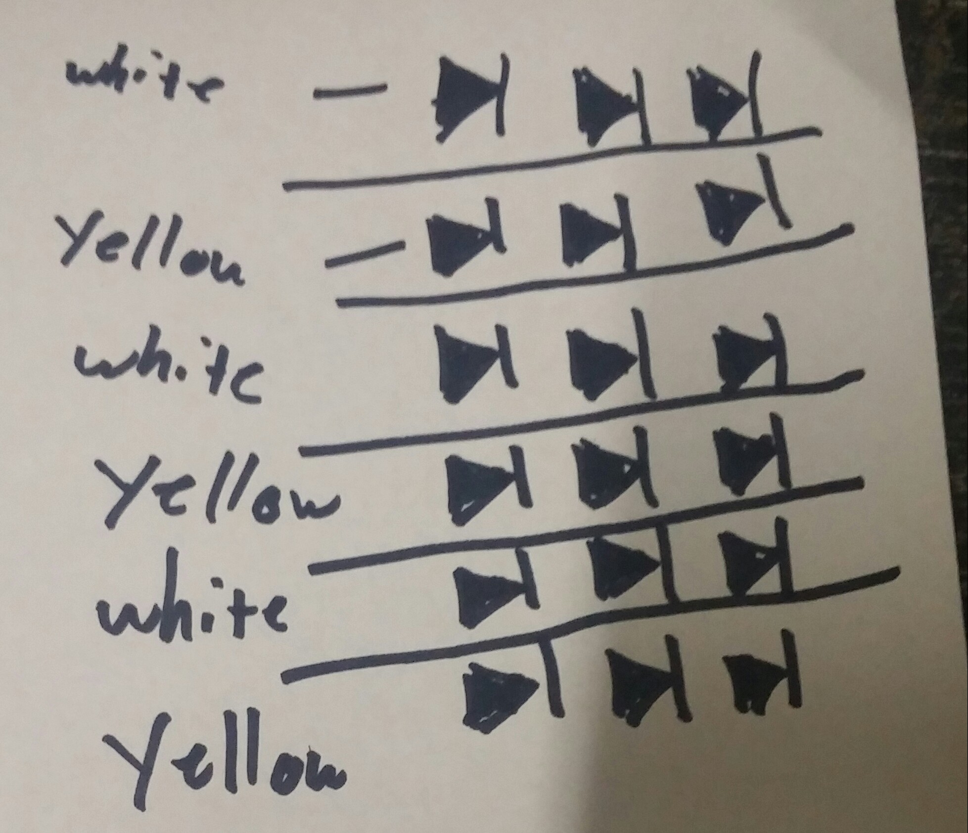
I'm sorry for the lack of detail. I will post a few horribly drawn pictures below to help explain what i meant. I forgot to add in the first post this is going to be battery powered.
On the 3x6 string it is a total of 18 bulbs, 9 white, 9 yellow. If i can figure out a way to do the prefered 4x8 it will be the same 50/50 split
So my understanding is each output on the arduino can supply 5v 40 mA. So it seems like my options are to either keep each column under that 5v 40mA or use relays. (This is coming purely from google searches). it looks like to fit under the maxium mA on 3 of my LEDs I would have to use 12v, However that is over the maximum voltage. If i use 5 volts on 3 of my LEDs I am at 60 mA. When I started this post I thought 5v on 3 of my LEDS was under that 40mA cap.
Each row will be all on or all off. I would like to be able to turn all of the white ones on at the same time if possible. I know I am missing some really big and obvious that is right in front of my head. I am sure I left out a ton of needed detail.
So your 4x8 matrix would be 64 leds? If so, CrossRoads' suggestion looks like the easiest option.
What is the battery you want to use? Voltage and capacity?
You are correct that the max current from any Arduino pin is 40mA, but that is not a good idea for long term use. 20mA to 30mA is better for long life. Also there is a 200mA limit for the ATmega328 chip, ie. all pins together. And there are other limits too.
To overcome these limits you will need transistors or an extra chip such as uln2803 or tpic6b595 or max7219 as suggested.
This diagram shows MAX7219 driving 4 columns of 8 LEDs, it supports up to 8 columns of 8.
You can partially populate each column, or fully populate them and under software control just turn on 4. There is a lot of flexibility.
The MAX7219 takes care of the multiplexing, turning on one column at a time with the pattern you sent it for that column:
digitalWrite (chipSelect, LOW);
SPI.transfer(registerAddress); // 0x01 to 0x08
SPI.transfer(columnData); // pattern for that column
digitalWrit (chipSelect, HIGH);
Repeat for each column as needed. Write the data once, the MAX7219 takes care of getting it displayed until you change it.
Relays are not a good choice. Don't make this harder than it needs to be.
So your 4x8 matrix would be 64 leds? If so, CrossRoads' suggestion looks like the easiest option.
My brain is fried. I messed up the math. 18 and 32 LEDS respectively.
CrossRoads:
This diagram shows MAX7219 driving 4 columns of 8 LEDs, it supports up to 8 columns of 8.
You can partially populate each column, or fully populate them and under software control just turn on 4. There is a lot of flexibility.
The MAX7219 takes care of the multiplexing, turning on one column at a time with the pattern you sent it for that column:
digitalWrite (chipSelect, LOW);
SPI.transfer(registerAddress); // 0x01 to 0x08
SPI.transfer(columnData); // pattern for that column
digitalWrit (chipSelect, HIGH);
Repeat for each column as needed. Write the data once, the MAX7219 takes care of getting it displayed until you change it.
Relays are not a good choice. Don't make this harder than it needs to be.

The Max7219 looks like it would definitely do it. Do you know of any resources where I could learn how to use use/install it? I'll be the first to admit I work with my back and not my brain for living and there is a reason for that. In my head when i see that I see a chip that I would assume I just solder things too. Would googling "multiplex project" help? I am just wanting to learn.
FYI, rapid flashing with relays is not a good idea. They can only switch at relatively low speeds, and if you push them, they make a terrible noise and wear out in no time. To make matters worse, an Arduino cannot operate a relay directly because relay coils usually need more than 40mA. So you have to use transistors to drive the relay coils (Arduino relay boards have the transistors built in). But if you are going to use transistors, you might as well drive the leds directly and forget the relays.
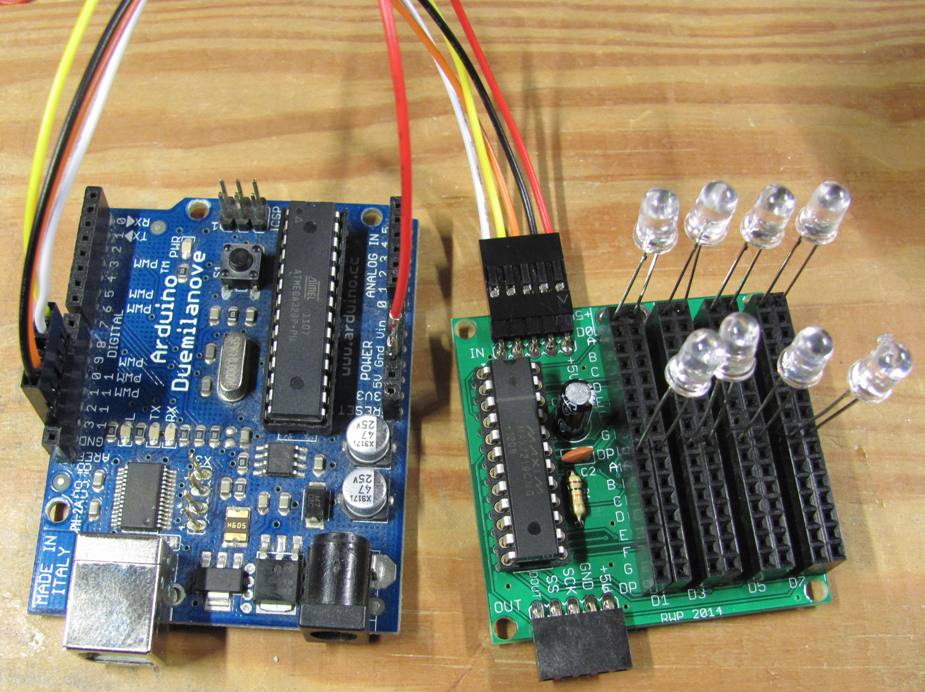
I offer a board with the chip and LEDs broken out - you just to connect the LEDs in pairs to the provided holes and lay them out how you want as one option: http://www.crossroadsfencing.com/BobuinoRev17/
You can wire each LED to a pair of male header pins and plug those into the female headers, or put male headers on the board and run a pair of wires to each LED. 30 AWG wirewrap wire works well for either one. I have a picture somewhere with a few LEDs wired up showing that.
I will have to read up on transistors more. But a 5 minute Google search seems to show that it is a fairly simple way to acomplish what I'm trying to do.
Looking at your drawings in post #3, a single TPIC6B595 could control 8 groupings of 7 or 8 LEDs in parallel from 5V.
Each output can sink 150mA continuously.
It is just a shift register, so all would do is shift in 1s for the outputs you wanted to turn on.
Or, you could wire up 8 discrete transistors and base or gate resistors. I'd recommend AOI510, an Arduino can control it directly. I use 32 of them on this board, with Arduino sending data into four 74HC595 shift registers to drive the N-channel MOSFET gates.
How durable are transistors compared to the shift register? I read online that relays aren't very reliable, but couldn't see how long term use would be with transistors and I didn't see any issues with shift registers. Either way I will have to finish making up my mind tonight so I have a chance of getting the parts early next week. I really with we had stores locally that had these types of parts.
They are as durable as you want. So long as you keep within the published specifications for current, heat etc, then the electronics will last basically forever.
The MAX7219 is a great chip because it is a proper current supply. It doesn't just output a voltage and let the LED get what it gets. It monitors the current through each individual LED (or string of LEDs) and actively adjusts it. If you have one group of LEDs a long distance away on thin wires that drop a lot of voltage, they will still be the same brightness as the ones on short wires.
However, if you have a mix of different LEDs then they may appear to have different brightnesses when they have identical current. This can be important for displays. Probably not too significant for your strobe application. If it is important, then a separate MAX7219 for each colour is necessary. Fortunately they daisy-chain very well so you don't use any more Arduino pins to drive them.
I think I am going to go on the MAX7219 that CrossRoads and MorganS suggested. is that 30 AWG the wire I want to buy? It just dawned on me that the spools of 10 gauge and 8 gauge I have will be way too large.
10 and 8 gauge is awkward to handle. It is difficult to bend it and make it stay.
30 gauge is really tiny. That's only used for very small signals.
If the wire lengths are significant, like more than 5 ft, then you should use an online calculator to estimate the voltage drop over the wire. Don't forget to include the return wire in the total length. Then you will know what wire gauge is required.