Strong flickering with multiplexed 10 x 10 LED matrix

Hello,

We’re absolute beginners when it comes to multiplexing in particular, so please forgive us our ignorance because we just wanted to learn a bit about this topic with this project. Please also let us know if we forgot any crucial bit of information.

Our plan

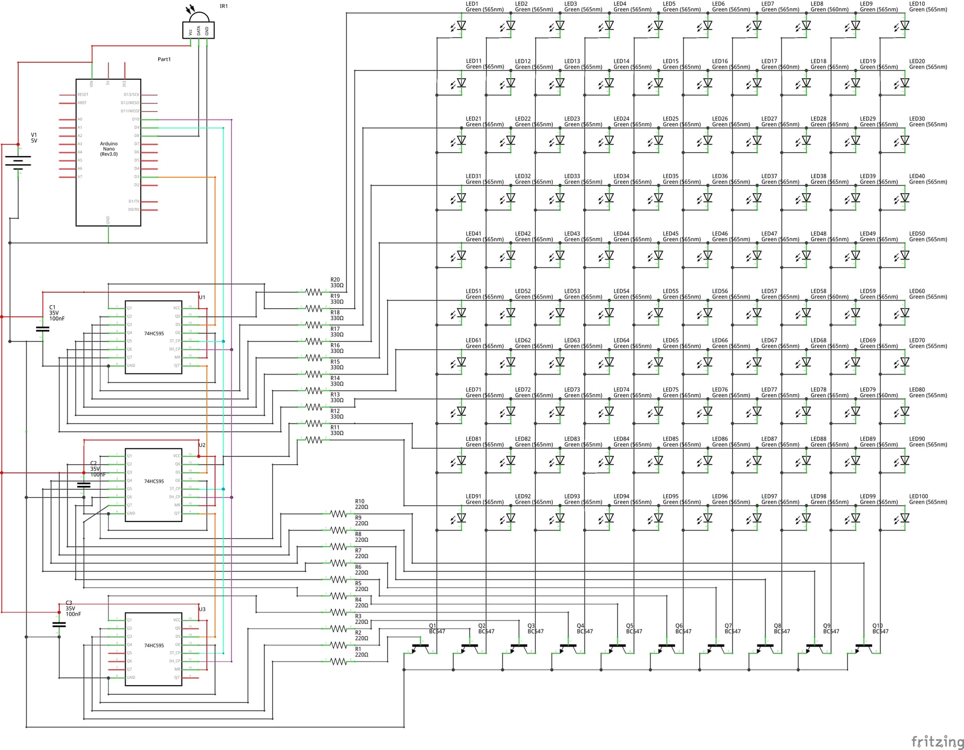
We want to make a 10 x 10 LED matrix controlled by daisy-chained shift registers. The idea is that each register pin can control one row or one column of the LEDs so we can use multiplexing to show some patterns. The standard stuff.

The problem at the moment is although the goal is generally achieved in the sense I can display a pttern, the LEDs are always flickering at a high frequency and also relatively faint, which affects all LEDs at the same time. In addition, there also lower frequency flickering that affects whole rows. This in in principle could be less than perfect connections because so far we only wired it with breadboards. Tomorrow I was planning to use perfboard. The LEDs are currently connect via 330 Ohm resistors is that too much?

Solutions tried so far

  1. Powering everything from the Arduino Nano or plugging a USB-c power jacket/power data module doesn’t really matter.
  2. We also played extensively with the delays.
  3. We also placed the Arduino Nano with an old Arduino Uno.
  4. Maybe my knowledge is too limited but in other posts and tutorials I didn’t find many differences (e.g. Multiplexing With Arduino and the 74HC595 : 14 Steps (with Pictures) - Instructables ).

Components

The led we uses are green (the shop says 3-3.4 V) and an Arduino Nano. The transistors are BC547.

Wiring diagram

Code

const int latchPin = 3;   // RCLK (shared)
const int clockPin = 4;   // SRCLK (shared)
const int dataPin = 5;    // SER

// Matrix dimensions
const int NUM_ROWS = 10;
const int NUM_COLS = 10;

// Corrected heart animation frames (10x10 matrices)
bool heartFrames[4][10][10] = {
  { // Frame 0: Small heart
    {0,0,0,0,0,0,0,0,0,0},
    {0,0,0,0,0,0,0,0,0,0},
    {0,0,0,0,0,0,0,0,0,0},
    {0,0,0,0,1,1,0,0,0,0},
    {0,0,0,1,1,1,1,0,0,0},
    {0,0,0,1,1,1,1,0,0,0},
    {0,0,0,0,1,1,0,0,0,0},
    {0,0,0,0,0,0,0,0,0,0},
    {0,0,0,0,0,0,0,0,0,0},
    {0,0,0,0,0,0,0,0,0,0}
  },
  { // Frame 1: Medium heart
    {0,0,0,0,0,0,0,0,0,0},
    {0,0,0,0,0,0,0,0,0,0},
    {0,0,0,1,0,0,1,0,0,0},
    {0,0,1,1,1,1,1,1,0,0},
    {0,1,1,1,1,1,1,1,1,0},
    {0,1,1,1,1,1,1,1,1,0},
    {0,0,1,1,1,1,1,1,0,0},
    {0,0,0,1,1,1,1,0,0,0},
    {0,0,0,0,1,1,0,0,0,0},
    {0,0,0,0,0,0,0,0,0,0}
  },
  { // Frame 2: Large heart
    {0,0,0,0,0,0,0,0,0,0},
    {0,0,0,1,1,1,1,0,0,0},
    {0,0,1,1,1,1,1,1,0,0},
    {0,1,1,1,1,1,1,1,1,0},
    {1,1,1,1,1,1,1,1,1,1},
    {1,1,1,1,1,1,1,1,1,1},
    {0,1,1,1,1,1,1,1,1,0},
    {0,0,1,1,1,1,1,1,0,0},
    {0,0,0,1,1,1,1,0,0,0},
    {0,0,0,0,1,1,0,0,0,0}
  },
  { // Frame 3: Full heart
    {0,0,0,0,0,0,0,0,0,0},
    {0,0,0,1,1,1,1,0,0,0},
    {0,0,1,1,1,1,1,1,0,0},
    {0,1,1,1,1,1,1,1,1,0},
    {1,1,1,1,1,1,1,1,1,1},
    {1,1,1,1,1,1,1,1,1,1},
    {1,1,1,1,1,1,1,1,1,1},
    {0,1,1,1,1,1,1,1,1,0},
    {0,0,1,1,1,1,1,1,0,0},
    {0,0,0,1,1,1,1,0,0,0}
  }
};

void setup() {
  pinMode(latchPin, OUTPUT);
  pinMode(clockPin, OUTPUT);
  pinMode(dataPin, OUTPUT);
}

void loop() {
  // Persistent scanning of current frame, change frame by elapsed time
  static int frame = 0;
  static unsigned long lastFrameChange = 0;
  unsigned long now = millis();
  unsigned long frameInterval = 500; // Faster animation
  displayMatrixFrame(heartFrames[frame]);
  if (now - lastFrameChange > frameInterval) {
    frame = (frame + 1) % 4;
    lastFrameChange = now;
  }
}

void displayMatrixFrame(bool matrix[10][10]) {
  for (int row = 0; row < 10; row++) {
    uint16_t rowPattern = (1 << row);
    uint16_t colPattern = 0;
    for (int col = 0; col < 10; col++) {
      if (matrix[row][col]) {
        colPattern |= (1 << col);
      }
    }
    uint32_t pattern = ((uint32_t)colPattern << 10) | rowPattern;
    digitalWrite(latchPin, LOW);
    shiftOut(dataPin, clockPin, MSBFIRST, (pattern >> 16) & 0xFF);
    shiftOut(dataPin, clockPin, MSBFIRST, (pattern >> 8) & 0xFF);
    shiftOut(dataPin, clockPin, MSBFIRST, pattern & 0xFF);
    digitalWrite(latchPin, HIGH);
    // No delay for maximum speed
  }
}

The high-frequency flickering and faint LEDs are typical when using multiplexing without enough current per LED or with slow refresh.

One way to solve it is to separate the fast row scanning from the slower frame updates. The row scanning has to run continuously as fast as possible to keep LEDs bright and reduce flicker, while the frame only changes every 500 ms as per your code.

Your resistance is somewhat OK - you could probably get more brightness if you go to ~220 Ω for 5 V LEDs but try first with changing the way you row scanning works

may be something like this (typed here - totally untested)

const byte latchPin = 3;
const byte clockPin = 4;
const byte dataPin = 5;

const byte NUM_ROWS = 10;
const byte NUM_COLS = 10;
const unsigned int ROW_ON_TIME_US = 800; // on time for a row in µs

byte heartFrames[][NUM_ROWS][NUM_COLS] = {
  {
    {0, 0, 0, 0, 0, 0, 0, 0, 0, 0},
    {0, 0, 0, 0, 0, 0, 0, 0, 0, 0},
    {0, 0, 0, 0, 0, 0, 0, 0, 0, 0},
    {0, 0, 0, 0, 1, 1, 0, 0, 0, 0},
    {0, 0, 0, 1, 1, 1, 1, 0, 0, 0},
    {0, 0, 0, 1, 1, 1, 1, 0, 0, 0},
    {0, 0, 0, 0, 1, 1, 0, 0, 0, 0},
    {0, 0, 0, 0, 0, 0, 0, 0, 0, 0},
    {0, 0, 0, 0, 0, 0, 0, 0, 0, 0},
    {0, 0, 0, 0, 0, 0, 0, 0, 0, 0}
  },
  {
    {0, 0, 0, 0, 0, 0, 0, 0, 0, 0},
    {0, 0, 0, 0, 0, 0, 0, 0, 0, 0},
    {0, 0, 1, 0, 0, 0, 1, 0, 0, 0},
    {0, 0, 1, 1, 1, 1, 1, 1, 0, 0},
    {0, 1, 1, 1, 1, 1, 1, 1, 1, 0},
    {0, 1, 1, 1, 1, 1, 1, 1, 1, 0},
    {0, 0, 1, 1, 1, 1, 1, 1, 0, 0},
    {0, 0, 0, 1, 1, 1, 1, 0, 0, 0},
    {0, 0, 0, 0, 1, 1, 0, 0, 0, 0},
    {0, 0, 0, 0, 0, 0, 0, 0, 0, 0}
  },
  {
    {0, 0, 0, 0, 0, 0, 0, 0, 0, 0},
    {0, 0, 0, 1, 1, 1, 1, 0, 0, 0},
    {0, 0, 1, 1, 1, 1, 1, 1, 0, 0},
    {0, 1, 1, 1, 1, 1, 1, 1, 1, 0},
    {1, 1, 1, 1, 1, 1, 1, 1, 1, 1},
    {1, 1, 1, 1, 1, 1, 1, 1, 1, 1},
    {0, 1, 1, 1, 1, 1, 1, 1, 1, 0},
    {0, 0, 1, 1, 1, 1, 1, 1, 0, 0},
    {0, 0, 0, 1, 1, 1, 1, 0, 0, 0},
    {0, 0, 0, 0, 1, 1, 0, 0, 0, 0}
  },
  {
    {0, 0, 0, 0, 0, 0, 0, 0, 0, 0},
    {0, 0, 0, 1, 1, 1, 1, 0, 0, 0},
    {0, 0, 1, 1, 1, 1, 1, 1, 0, 0},
    {0, 1, 1, 1, 1, 1, 1, 1, 1, 0},
    {1, 1, 1, 1, 1, 1, 1, 1, 1, 1},
    {1, 1, 1, 1, 1, 1, 1, 1, 1, 1},
    {1, 1, 1, 1, 1, 1, 1, 1, 1, 1},
    {0, 1, 1, 1, 1, 1, 1, 1, 1, 0},
    {0, 0, 1, 1, 1, 1, 1, 1, 0, 0},
    {0, 0, 0, 1, 1, 1, 1, 0, 0, 0}
  }
};
const uint8_t numFrames = sizeof heartFrames / sizeof *heartFrames;

uint8_t currentFrame = 0;
unsigned long lastFrameChange = 0;
const unsigned long frameInterval = 500;

void setup() {
  pinMode(latchPin, OUTPUT);
  pinMode(clockPin, OUTPUT);
  pinMode(dataPin, OUTPUT);
}

void loop() {
  unsigned long now = millis();
  if (now - lastFrameChange > frameInterval) {
    currentFrame = (currentFrame + 1) % numFrames;
    lastFrameChange = now;
  }
  scanRow(heartFrames[currentFrame]);
}

void scanRow(byte matrix[NUM_ROWS][NUM_COLS]) {
  static int row = 0;
  uint16_t rowPattern = (1 << row);
  uint16_t colPattern = 0;
  for (int col = 0; col < NUM_COLS; col++) {
    if (matrix[row][col] == 1) colPattern |= (1 << col);
  }
  uint32_t pattern = ((uint32_t)colPattern << NUM_ROWS) | rowPattern;
  digitalWrite(latchPin, LOW);
  shiftOut(dataPin, clockPin, MSBFIRST, (pattern >> 16) & 0xFF);
  shiftOut(dataPin, clockPin, MSBFIRST, (pattern >> 8) & 0xFF);
  shiftOut(dataPin, clockPin, MSBFIRST, pattern & 0xFF);
  digitalWrite(latchPin, HIGH);
  row = (row + 1) % NUM_ROWS;
  delayMicroseconds(ROW_ON_TIME_US);
}

1 Like

Your schematic is a good attempt for a beginner, but it is like a maze puzzle. A schematic should be as simple and easy to understand as possible. Try to arrange the components so that there are as few lines criss-crossing each other as possible. Use the +V and GND symbols as many times as you need and wherever they are needed so that you don't have the +V and ground lines criss-crossing other lines.

I did spot one error in your schematic. You have 5V connected to the Vin pin of the Nano. The Vin pin needs at least 6.5 to 7V. If your 5V power supply is regulated and you have confirmed with your multimeter that it is outputting 5V, you can connect it to the 5V pin on the Nano.

2 Likes

You are presenting as a group, is this a school project?

Here, you are setting constants for your matrix size but not using them!

EDIT: @J-M-L already fixed that for you in his version.

1 Like

Unless part of the exercise is "working with what you've got", if you add another '595 - having then 2 for ROWs and 2 for COLs - things will go easier.

1 Like

I suggest adding one or more electrolytic capacitors to the circuit, perhaps 47uF or 100uF, across the 5V and ground wires, close to the transistors. This will act as a local reservoir of charge/current, close to the transistors which switch the current between the columns, so that the sudden changes in current, when the columns switch, is smoothed out.

1 Like

Not sure if you would get ghosting with this setup, since the row and column switch simultaneously. Typically all columns would be turned off while changing the pattern, to prevent briefly flashing the next column pattern on the previous column.

Hi. I think the work has been done perfectly.

To minimize flickering, the multiplex must be triggered with the most consistent timing possible, and all other program operations must comply with this timing constraint.

void loop() 
{
    if (micros() - scanTime  >=  2000)
    {
        scanRow(heartFrames[currentFrame]);
        scanTime += 2000;
        unsigned long now = millis();
        if (now - lastFrameChange > frameInterval) {
            currentFrame = (currentFrame + 1) % numFrames;
            lastFrameChange = now;
        }
    }
}

This way, the start of the scanRow function is kept as synchronized as possible with a constant 2 ms period (50 Hz display refresh). Inside scanRow, the display should be updated immediately (about 400 µs for the three shiftOut calls), and then, in the remaining 1600 µs, all other tasks can be performed, including the calculations to build the next pattern.

void scanRow(byte matrix[NUM_ROWS][NUM_COLS]) 
{
    static int row = 0;
    uint16_t rowPattern = (1 << row);
    uint16_t colPattern = 0;
    digitalWrite(latchPin, LOW);
    shiftOut(dataPin, clockPin, MSBFIRST, (pattern >> 16) & 0xFF);
    shiftOut(dataPin, clockPin, MSBFIRST, (pattern >> 8) & 0xFF);
    shiftOut(dataPin, clockPin, MSBFIRST, pattern & 0xFF);
    digitalWrite(latchPin, HIGH);
    for (int col = 0; col < NUM_COLS; col++) {
        if (matrix[row][col] == 1) colPattern |= (1 << col);
    }
    uint32_t pattern = ((uint32_t)colPattern << NUM_ROWS) | rowPattern;
    row = (row + 1) % NUM_ROWS;
}
1 Like

No need to build the column pattern repeatedly, store the binary representation of the pattern instead of using a bool for each bit.

2 Likes

We still have a lot 74HC595s but we can also easily buy more. Things are very cheap here. Previous attempts of using two sets of daisy-chained shift registers failed but we probably didn’t use them correctly.

So, for that plan we need to have a unique data line and latch pin for each set of shift registers while the clock can be shared?

We will come back after trying all the suggestions and report what makes a difference.

No, you can chain the shift registers so only one data line is needed. You already know this.

I'm not sure why @runaway_pancake recommended more shift registers. It would have made the coding slightly easier, but you already did the slightly more difficult coding needed for using 3 shifts registers, and I don't think there is a problem with that coding.

I can see several ways to improve the code you have, but I am not sure why the coding you have now causes all the flickering you described. One theory I have is:

What's important here is not maximum speed. The speed only needs to be fast enough to avoid visible flicker, which should be easy enough to achieve. What's more important is consistent timing to give a steady display with even brightness.

The code suggested by @J-M-L should achieve more steady timing. I will be interested to here how that code performs.

Here is my suggestion to improve the efficiency of your code. @david_2018 is suggesting the same change.

(This probably won't fix the flickering issues. )

// Corrected heart animation frames (10x10 matrices)
bool heartFrames[4][10][10] = {
  { // Frame 0: Small heart
    {0,0,0,0,0,0,0,0,0,0},
    {0,0,0,0,0,0,0,0,0,0},
    {0,0,0,0,0,0,0,0,0,0},
    {0,0,0,0,1,1,0,0,0,0},
    {0,0,0,1,1,1,1,0,0,0},
    {0,0,0,1,1,1,1,0,0,0},
    {0,0,0,0,1,1,0,0,0,0},
    {0,0,0,0,0,0,0,0,0,0},
    {0,0,0,0,0,0,0,0,0,0},
    {0,0,0,0,0,0,0,0,0,0}
  },

becomes:

// Corrected heart animation frames (10x10 matrices)
uint16_t heartFrames[4][10] = {
  { // Frame 0: Small heart
    0b0000000000,
    0b0000000000,
    0b0000000000,
    0b0000110000,
    0b0001111000,
    0b0001111000,
    0b0000110000,
    0b0000000000,
    0b0000000000,
    0b0000000000
  },
//repeat similar change for the other frames

Now, each frame consumes only 20 bytes of memory instead of 100 bytes. Plus, much bit-manipulation can be avoided, making the code execute faster.

void displayMatrixFrame(bool matrix[10][10]) {
  for (int row = 0; row < 10; row++) {
    uint16_t rowPattern = (1 << row);
    uint16_t colPattern = 0;
    for (int col = 0; col < 10; col++) {
      if (matrix[row][col]) {
        colPattern |= (1 << col);
      }
    }

becomes:

void displayMatrixFrame(uint16_t matrix[10]) {
  for (int row = 0; row < 10; row++) {
    uint16_t rowPattern = (1 << row);
    uint16_t colPattern = matrix[row];

This may seem to have removed only a couple of lines of code, but they are the most frequently executed lines in the whole sketch.

Same here - wonder if you saw any improvement

Hello everyone, don’t let the video fool you. The flickering in real life now is barely visible and doesn’t bother at all but we still feel it’s a bit faint but maybe this is just how good it gets with multiplexing. Also, there seem to be a gradient where the middle of the pattern is fainter than the periphery. Not sure if that is visible in the video.

output

Here is what we did and how it effects the LED matrix:

  • We made sure that the USB power, which measures to be 5V, is connected to the 5V Arduino pin not Vin. This however did not change the main problem but is probably a smart thing to do regardless.
  • We now placed the 104 ceramic capacitors really close to the shift registers. Now cables first go off the +/- rail on the breadboard, then connect to the capacitors and lines then go into the 5V & GND of the registers. Previously, there were just capacitors on the +/- rail. The strong flickering is gone.
  • The code by @J-M-L works better for sure ( Strong flickering with multiplexed 10 x 10 LED matrix - #2 by J-M-L ) but there are problems with the pattern it displays.
  • We couldn't get this code to work ( Strong flickering with multiplexed 10 x 10 LED matrix - #10 by Claudio_FF ).
  • To increase the brightness, we now switched to 240 Ohm resistors because we didn't have 220 Ohm anymore. Honestly, this didn’t change much.
  • We also change ROW_ON_TIME_US = 1600, higher numbers create flickering but the LEDs are still faint. The flickering is kind of expected. Lowering the value also doesn't change anything.
  • Provided we measured correctly, we're drawing between 60 mA and 160 mA. Everything currently powered by the module below. Maybe one could use a better power source?

In conclusion, we think the main problem was that we did not actually place the small ceramic capacitor where we said we did in the drawing.

Remaining problems

  • Even after trying hard, we were unable to fix the pattern (see video).
  • The registers should connect to the LEDs in the following manner:
Register Output pin Connection
1 1 Row 1
1 2 Row 2
1 3 Row 3
1 4 Row 4
1 5 Row 5
1 6 Row 6
1 7 Row 7
1 8 Row 8
2 1 Row 9
2 2 Row 10
2 3 Column 1
2 4 Column 2
2 5 Column 3
2 6 Column 4
2 7 Column 5
2 8 Column 6
3 1 Column 7
3 2 Column 8
3 3 Column 9
3 4 Column 10
3 5 No connection
3 6 No connection
3 7 No connection
3 8 No connection

Current code

const byte latchPin = 3;
const byte clockPin = 4;
const byte dataPin = 5;

const byte NUM_ROWS = 10;
const byte NUM_COLS = 10;
const unsigned int ROW_ON_TIME_US = 800; // on time for a row in µs
//const unsigned int ROW_ON_TIME_US = 1600; // on time for a row in µs

byte heartFrames[][NUM_ROWS][NUM_COLS] = {
  {
    {0, 0, 0, 0, 0, 0, 0, 0, 0, 0},
    {0, 0, 0, 0, 0, 0, 0, 0, 0, 0},
    {0, 0, 0, 0, 0, 0, 0, 0, 0, 0},
    {0, 0, 0, 0, 1, 1, 0, 0, 0, 0},
    {0, 0, 0, 1, 1, 1, 1, 0, 0, 0},
    {0, 0, 0, 1, 1, 1, 1, 0, 0, 0},
    {0, 0, 0, 0, 1, 1, 0, 0, 0, 0},
    {0, 0, 0, 0, 0, 0, 0, 0, 0, 0},
    {0, 0, 0, 0, 0, 0, 0, 0, 0, 0},
    {0, 0, 0, 0, 0, 0, 0, 0, 0, 0}
  },
  {
    {0, 0, 0, 0, 0, 0, 0, 0, 0, 0},
    {0, 0, 0, 0, 0, 0, 0, 0, 0, 0},
    {0, 0, 1, 0, 0, 0, 1, 0, 0, 0},
    {0, 0, 1, 1, 1, 1, 1, 1, 0, 0},
    {0, 1, 1, 1, 1, 1, 1, 1, 1, 0},
    {0, 1, 1, 1, 1, 1, 1, 1, 1, 0},
    {0, 0, 1, 1, 1, 1, 1, 1, 0, 0},
    {0, 0, 0, 1, 1, 1, 1, 0, 0, 0},
    {0, 0, 0, 0, 1, 1, 0, 0, 0, 0},
    {0, 0, 0, 0, 0, 0, 0, 0, 0, 0}
  },
  {
    {0, 0, 0, 0, 0, 0, 0, 0, 0, 0},
    {0, 0, 0, 1, 1, 1, 1, 0, 0, 0},
    {0, 0, 1, 1, 1, 1, 1, 1, 0, 0},
    {0, 1, 1, 1, 1, 1, 1, 1, 1, 0},
    {1, 1, 1, 1, 1, 1, 1, 1, 1, 1},
    {1, 1, 1, 1, 1, 1, 1, 1, 1, 1},
    {0, 1, 1, 1, 1, 1, 1, 1, 1, 0},
    {0, 0, 1, 1, 1, 1, 1, 1, 0, 0},
    {0, 0, 0, 1, 1, 1, 1, 0, 0, 0},
    {0, 0, 0, 0, 1, 1, 0, 0, 0, 0}
  },
  {
    {0, 0, 0, 0, 0, 0, 0, 0, 0, 0},
    {0, 0, 0, 1, 1, 1, 1, 0, 0, 0},
    {0, 0, 1, 1, 1, 1, 1, 1, 0, 0},
    {0, 1, 1, 1, 1, 1, 1, 1, 1, 0},
    {1, 1, 1, 1, 1, 1, 1, 1, 1, 1},
    {1, 1, 1, 1, 1, 1, 1, 1, 1, 1},
    {1, 1, 1, 1, 1, 1, 1, 1, 1, 1},
    {0, 1, 1, 1, 1, 1, 1, 1, 1, 0},
    {0, 0, 1, 1, 1, 1, 1, 1, 0, 0},
    {0, 0, 0, 1, 1, 1, 1, 0, 0, 0}
  }
};
const uint8_t numFrames = sizeof heartFrames / sizeof *heartFrames;

uint8_t currentFrame = 0;
unsigned long lastFrameChange = 0;
const unsigned long frameInterval = 500;

void setup() {
  pinMode(latchPin, OUTPUT);
  pinMode(clockPin, OUTPUT);
  pinMode(dataPin, OUTPUT);
}

void loop() {
  unsigned long now = millis();
  if (now - lastFrameChange > frameInterval) {
    currentFrame = (currentFrame + 1) % numFrames;
    lastFrameChange = now;
  }
  scanRow(heartFrames[currentFrame]);
}

void scanRow(byte matrix[NUM_ROWS][NUM_COLS]) {
  static int row = 0;
  uint16_t rowPattern = (1 << row);
  uint16_t colPattern = 0;
  for (int col = 0; col < NUM_COLS; col++) {
    if (matrix[row][col] == 1) colPattern |= (1 << col);
  }
  uint32_t pattern = ((uint32_t)colPattern << NUM_ROWS) | rowPattern;
  digitalWrite(latchPin, LOW);
  shiftOut(dataPin, clockPin, MSBFIRST, (pattern >> 16) & 0xFF);
  shiftOut(dataPin, clockPin, MSBFIRST, (pattern >> 8) & 0xFF);
  shiftOut(dataPin, clockPin, MSBFIRST, pattern & 0xFF);
  digitalWrite(latchPin, HIGH);
  row = (row + 1) % NUM_ROWS;
  delayMicroseconds(ROW_ON_TIME_US);
}
1 Like

Green LEDs typically have a voltage drop of 2.2 volts or more, so you would have a maximum current of just under 12mA, not even normal full brightness for most LEDs. Typically a multiplexed LED will run much higher current than the “normal” full brightness current, with a limitation on duty cycle, so that the brightness is somewhere near a non-multiplexed LED.

As an examples, one datasheet I looked at for a green LED showed a typical forward current of 20mA, with an absolute maximum continuous current of 25mA, and a maximum of 140mA if the LED is turned on for 0.1mS at 1/10 duty cycle.

You will never achieve a bright display using the 74HC595, much better to use a TPIC6B595 which has a higher current capacity. You would need to reconfigure the matrix, since the TPIC6B595 can only drive this current in a LOW state.

You must have a hardware problem, possibly with the wiring, because printing out the contents of the “pattern” variable shows the correct LED pattern. It is interesting in your video that the entire right column of LEDs are never lit.

Try displaying a pattern that only shows a single column or row of LEDs at a time, to verify that the wiring is correct.

For future reference, I think this can be done without shift registers. The row anodes would be sourced by 10 GPIO pins through current-limiting resistors. The columns would be sunk by the 10 outputs of the magical CD4017 or 74HC4017, each driving an NPN transistor with a base resistor. The 4017 switches (high) to the next column simply by toggling its clock line. No shift registers are needed.

This could all be updated at a fixed rate with an ISR triggered by the millis() clock if 1ms is fast enough. Each lit LED would be turned on 1/10th of the time. My memory is that 2ms works ok for 1/4, so 1ms might just be fast enough for 1/10.

The ISR would turn all of the row outputs off, then clock the 4017 to the next column, then turn on the row outputs that should be lit for that column. Then it would pre-calculate the row outputs that should be turned on at the next interrupt. This would all be in the background unnoticed by the loop(), and unaffected by any delays found in the loop().

If the LEDs could be limited to 2.5mA each when lit (high-efficiency LEDs might do that), then things could be further simplified by moving the HC4017 up to drive the rows directly, with no transistors or resistors, and then the columns would be driven by the GPIOs directly with a 1K current limiting resistor. The 4017 would cycle through the rows one at a time, and the column GPIOs would be turned on for the columns in which that row is to be lit. No transistors, and only one resistor each on the columns. The 2.5mA is the HC4017's 25mA maximum output current divided by up to 10 lit LEDs in the row.

I seem to recall that a 50Hz refresh rate is needed to eliminate the appearance of flickering. Ten columns at a 50Hz rate would be 500Hz, well below the interrupt rate for the timer used for millis (which is actually 976.5625Hz, not 1000Hz).

I’ve used this technique for multiplexing displays, driving the interrupt off the timer0 compare register so that it occurs midway between the interrupt for millis (which uses the timer0 overflow interrupt). See the following for details on setting up the timer0 interrupt https://learn.adafruit.com/multi-tasking-the-arduino-part-2/timers