Hi there. I'm struggling with noisy PPM on my arduino Nano. I am using a radiomaster tx16s as my TX and my RX is a flysky FS-iA10B.
My tx is set to PPM/iBus
Here are some details on the wiring.
Receiver is powered by a 5v bec on the vcc side.
Ppm wire goes from signal on channel 1 (top, signal pin) straight to pin 4 on my Nano (digital pin with interrupt).
My Nano is powered by 5v from my receiver. Power goes to VIN and ground goes to GND.
I've used various codes and libraries online. They all end up with the same issue. Lots of noise and lots of interference.
If I plug my RX into my drone FC. The ppm signal is smooth and reliable. I can get all 8 channels.
My project is to use servos to drive an ornithopter. I have been shared the code I need but I need ppm signal to work. I need help to either...
Figure out where the interference is coming from
Figure out where the noise is coming from
Figure out the ppm pattern since it might be different to other ppm values?
I don't have an oscilloscope. I don't have any displays for the Nano. I was hoping it would be a plug an play experience since the code was already written.
I can get ppm values written up on the serial plotter however... They are all over the place. 1 or 2 channels can be made out but if I hit a toggle switch for example, everything is all over the place.
Sorry I forgot to mention. I have a voltage regulator as well that I also tried powering the Nano via a voltage regulator putting out 8.4v. This voltage regulator in the future will be used to power the servos.
I'll double check when I get home where I currently have the power. I think it's on the 5v pin, but I wouldn't be surprised if I have left it on the Vin.
What do you mean? Powering the arduino isn't a problem. It's the ppm signal I'm having issue with. It does not matter how I power the board. Whether it's via 5v into the 5v pin, 8v into the Vin pin. I cannot get a clean ppm signal.
What i said was, while the arduino is at my pc. I used the 8.4v power for the servos to power the arduino. This is just for testing purposes. It won't be done like this in the aircraft...
So I've tested the receiver with one of my multi rotors. The flight controller picks up the ppm signal clearly. This is powering the receiver and FC using 5v.
The ppm signals between various brands are all the same. I have an old orange rx receiver that that has broken antennas. Ppm signal from that to the flight controller, all good.
I've just tried that orange rx receiver on the arduino. The ppm signal is exactly the same. It's all over the place.
Something, is messing up the signal between the rx and the arduino.
It's the custom here to post a detailed, if hand-drawn schematic showing all connections including the power stage of your circuit, as well as listing all your components (you mentioned switches - what switches, for example).
Also, posting your complete code using code tags is important as well, in order to give the most complete information to helpers here, many of whom with a high level of expertise, will simply pass your request for help by if you don't supply everything I've mentioned.
Any questions about what's required and why are well documented here:
Still getting bad values. Thank you for the suggestion!
The screenshot is what I see even if I use other PPM encoders in the library. The code in the photo is what was sent to me as a working project. All I needed to do was connect a PPM receiver and connect the servos.
Please post your sketch so I can replicate your setup.
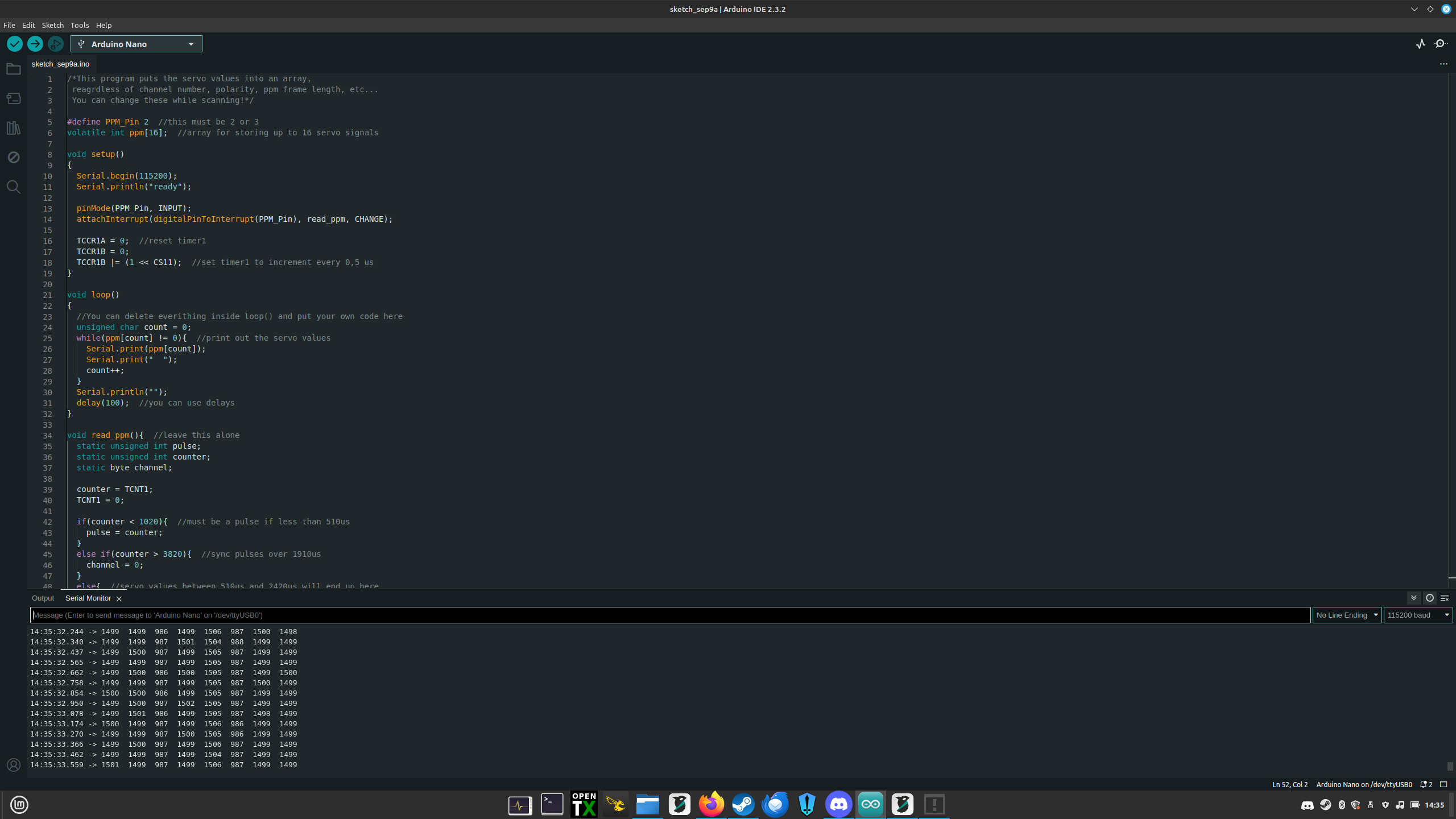
In the meantime here is a test sketch that prints the PPM channel values.
Connect your receiver PPM signal to pin 2
/*This program puts the servo values into an array,
 reagrdless of channel number, polarity, ppm frame length, etc...
 You can change these while scanning!*/

#define PPM_Pin 2  //this must be 2 or 3
volatile int ppm[16];  //array for storing up to 16 servo signals

void setup()
{
  Serial.begin(115200);
  Serial.println("ready");

  pinMode(PPM_Pin, INPUT);
  attachInterrupt(digitalPinToInterrupt(PPM_Pin), read_ppm, CHANGE);

  TCCR1A = 0;  //reset timer1
  TCCR1B = 0;
  TCCR1B |= (1 << CS11);  //set timer1 to increment every 0,5 us
}

void loop()
{
  //You can delete everithing inside loop() and put your own code here
  unsigned char count = 0;
  while(ppm[count] != 0){  //print out the servo values
    Serial.print(ppm[count]);
    Serial.print("  ");
    count++;
  }
  Serial.println("");
  delay(100);  //you can use delays
}

void read_ppm(){  //leave this alone
  static unsigned int pulse;
  static unsigned int counter;
  static byte channel;

  counter = TCNT1;
  TCNT1 = 0;

  if(counter < 1020){  //must be a pulse if less than 510us
    pulse = counter;
  }
  else if(counter > 3820){  //sync pulses over 1910us
    channel = 0;
  }
  else{  //servo values between 510us and 2420us will end up here
    ppm[channel] = (counter + pulse)/2;
    channel++;
  }
}
This is a snippet of the output I get if I connect a cheap 8ch drone receiver to it.
I never wrote the code I got sent. I don't know how it reads the PPM signal. The guy who wrote it kindly sent it to me because I asked him for advice. I don't feel I could share what he has sent to me publicly because he has put a lot of work into it. I could share you the sketch/project privately if you want to take a look at it?
This is a huge step forward never or less. In his video on youtube, he does have his aircraft flying. I'm happy It's not a hardware problem but now, I need to do some more learning... I'd much rather fix something with a screwdriver than do stuff with code.
Unless he sent me the wrong files? or there could be something commented out that I have missed? The error could still be down to me.