I'm a newbie at the Arduino project. I'm trying to do the project 2 spaceship interface. But I'm stuck on the first section' builds the circuit'. I did exactly the whole steps but still the leds won't light up. Has this something to do with the resistors? I'm not finding the resistors that they are asking for in the Box. Can somebody help me to do the first step of this project?
You are referring to this?

Resistors are required, however not necessarily those values.
What resistors do you have?
Did you verify the LEDs and switch are oriented correctly?
The LED short lead goes towards the resistor.
The switch is often installed incorrectly. This is very common. I struggled with the switch myself.
Try connecting 5 volts to a resistor to one LED leg and the other leg to ground.
5 ---- vxvxvxv----|>|-----GND
Leaving out any code or complications.
The LED may be in backwards, or you may have a wiring issue or, with some smallish probability, a defective LED.
Any resistor you have from 220 to 2200 ohms should work; be sure to use one always. If you ever did not, you may have broken that LED. It might have involved some excitement, it could have been silent.
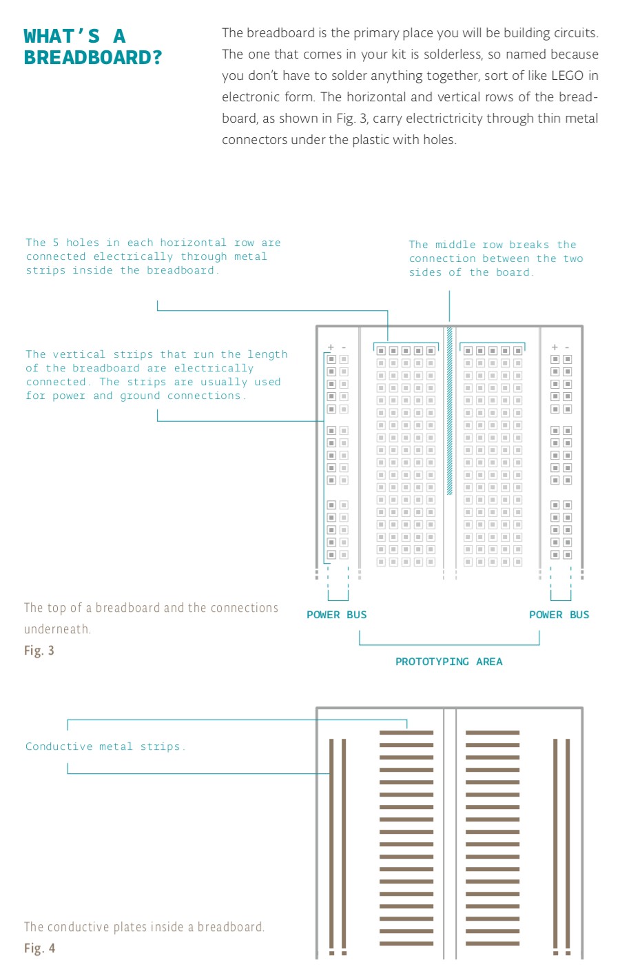
Are you confident in your knowledge of how the breadboard works to make connections amongst the things you plug into it?
a7
I'll trust you on the lead length, I can never remember. But it would be better to say it goes towards ground; the resistor is in series and could be placed on either side.
Most LEDs draw attention in some way to the cathode, current flowing from the anode to the cathode will illuminate the LED, which is nicely shown by the diode symbol which you can read like it is an arrow pointing the way.
5mm LEDs have a flat area on the base which indicates the cathode. 99.999 percent of the time, ask me how I know this is not always the case. Better yet, don't ask. ![]()
Here yes, the resistors are between the LED and ground, so.
a7
Short, Fat, Flat Cathode
I was literally going off the schematic diagram. I didn't want to overwhelm him.
I'll regress and step away.
Sry, I only meant to add.
As for short flat and fat, I appreciate the attempt, but will have to keep my little 8 milliamp tester handy in all cases. ![]()
a7
LOL once you remember short fat flat cathode you'll never have to guess again. It's no different than ELI the ICE Man or those bad boys and Violet putting out.
@barraz
Back on topic, you uploaded the Blink example sketch in the setup section of the tutorial. Did you get that to work?
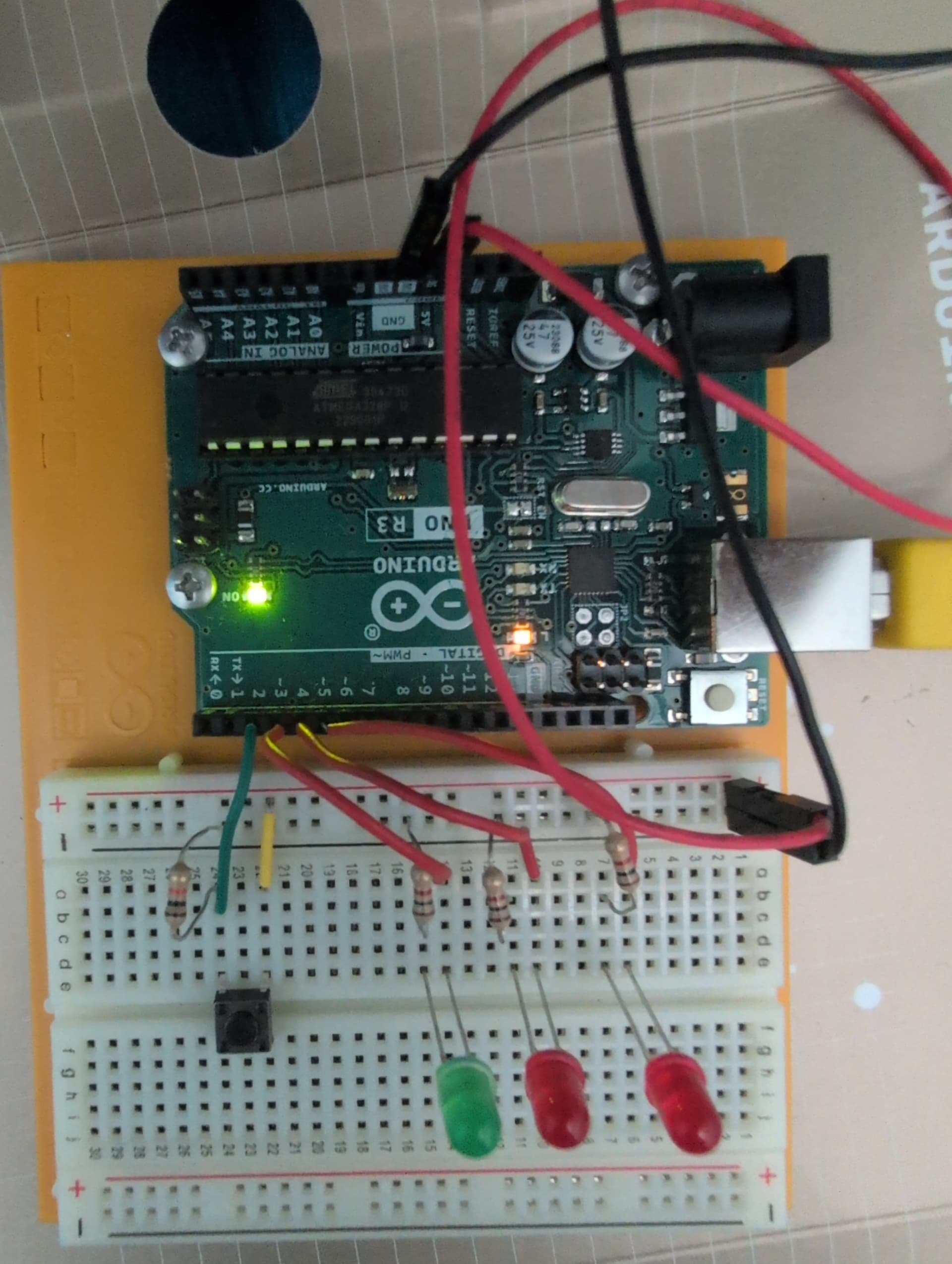
This is my setup. Thank you guys for the tips. Used all of y'all information. The LEDS won't work . I checked them all apart and they work individually. I put the long leg correctly.What am I doing wrong.

Hi @barraz. I see a problem here:
i
The resistor lead is inserted into row 12 of the breadboard, while the LED lead it is intended to be connected to is in row 11 of the breadboard.
From the picture, I can't tell whether that LED's jumper wire (the red wire connected to pin 4 on the UNO R3) is also shifted down one row from its intended connection at row 10 in the breadboard.

Now there are two new problems here:
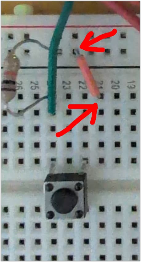
This jumper should connect the 5 V rail of the breadboard to row 22 on the breadboard. But you have it connecting the GND rail of the breadboard to row 21.
Fix that problem and then check to see if the project starts working as expected now.
What is your experience level with electronics and working with breadboards?
I'll ask the question differently,
Do you understand this schematic?
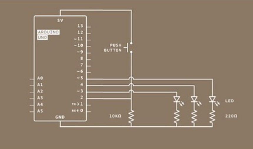
Or are you just trying to make your circuit look like this one?

Do you feel comfortable with how a breadboard works and how it's configured?
Have you properly uploaded the code without errors?
I'm a newbie. But I do understand the schematics.
It looks perfect now. This is excellent progress!
At least from looking at the copy of the Arduino Projects Book I have (which is from some years ago, so might be outdated), it seems like the book doesn't very clearly state this, but you must upload the Arduino sketch code to the UNO R3 board before it will behave as described in the book. This is different from the "Get To Know Your Tools" project (project 01), where you are actually only using the UNO R3 as a power supply and thus don't need to run any specific Arduino sketch program on the board for the project to work.
So please do this:
- Start Arduino IDE.
- Select File > New Sketch from the Arduino IDE menus.
A new Arduino sketch will open in an Arduino IDE window. - Replace the default code in the Arduino IDE editor with the code from the project book.
ⓘ Alternatively, you can simply select File > Examples > 10.StarterKit_BasicKit > p02_SpaceshipInterface from the Arduino IDE menus and the the pre-written code for the project will open in a new Arduino IDE window. - Connect your UNO R3 board to your computer with a USB cable.
- Select Tools > Board > Arduino AVR Boards > Arduino Uno from the Arduino IDE menus.
- Select the serial port of your board from Arduino IDE's Tools > Port menu.
- Select Sketch > Upload from the Arduino IDE menus.
- Wait for the upload process to finish successfully, as indicated by the temporary appearance of a "Done uploading." notification at the bottom right corner of the Arduino IDE window:

Now try pressing the button on your breadboard. Hopefully this time the LEDs will behave as described in the project book:
A green LED will be on, until you press a button. When the Arduino gets
a signal from the button, the green light will turn off and 2 other lights will start
blinking.
Thanks. I got it. As a newbie a didn't know you had to upload the code. it it wasn't clear in the book that I had to do that. Now I am understanding the whole concept. Thank you again for helping me out.