I'm frequently designing battery powered systems and I've used the nano board for some projects but the nano waste current in power down.
Why?
Because even if you set the MCU in power down, near 15 mA are drawn by the standard regulator and the FT232 Quiescent currents.
But a little nano hardware modification can solve this issue.
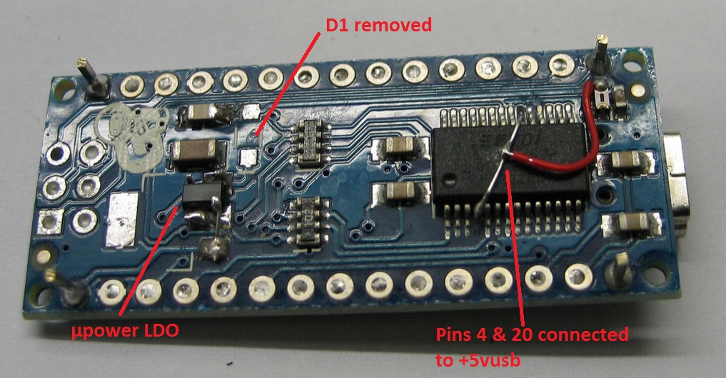
1-change the LDO by a low power one (I've used a sot-23-5 from an existing design)
2-disconnect the pin 4 and 20 from the +5v and connect them to the +5Vusb
3-best: remove the D1 shottky diode (to avoid reverse current to go to the FT232) but a copper jumper can be added in serie on the PCB to easily make the mod.
When it's done and with the right level on the digital pins (Tx = Rx = D13 = 0 to avoid current supply through pins) the current consumption drop from 4mA to 300µA when the board is in power down ready to be turned on by an external interrupt. (a logic signal turn on my 3A switching supply)
The FT232 works without problem when connected to the USB port.
here is a picture showing the modification