Hi, I am looking for some assistance with a custom board which is based on the Arduino Nano 33 BLE rev2 and is controlling some lighting and sensors. The Nano 33 BLE uses the NINA-B306 SoC from UBLOX and from my understanding it requires flashing the bootloader prior to being able to load firmware on the device.
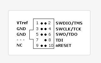
I have been using the SWD programmer JLINK Mini-EDU from Segger. I tested this on the Arduino Nano and was able to Program the device with the nano33ble bootloader.bin file.
When attempting this on the custom board I received this error:
Connecting to J-Link...
Bank selection: BankAddr=0x00000000 Enabled
Bank selection: BankAddr=0x12000000 Enabled
Loader selection: BankAddr=0x00000000 Loader=Default
Loader selection: BankAddr=0x12000000 Loader=SCK@P017_CSN@P019_IO0@P020_IO1@P021_IO2@P022_IO3@P023
Connecting to target...
ERROR: Could not connect to target.
Done.
When using the Arduino Nano 33 BLE this is the message exactly the same message except it Connected to the target and successfully downloaded.
I’ve followed Seggers troubleshooting and verified correct voltage on VTref = 3.3V and the connections are correctly soldered to test points.
The rev2 of the 33 BLE board removes pull up resistors for RESETN and SWDCLK. I did try removing these and still received the same error.
Is there anything obviously wrong with the schematic?

Here is a description of the GPIO are being used for:
GPIO3 = toggles a transistor switch for enabling a fan, 10k pull down.
GPIO4 = internal RGB LED, green segment, 2 mA
GPIO5 = internal RGB LED, red segment, 2 mA
GPIO7 = not used
GPIO16 = tactile switch input, active low.
GPIO17 = interrupt, pulled high to 3.3V.
GPIO18 = SCL, pulled high to 3.3V.
GPIO20 = SDA, pulled high to 3.3V.
GPIO21= PWM output, pulled low.
GPIO22 = output to trigger haptic motor, pulled low.
GPIO23 = digital input, pulled low, active high.
GPIO24 = external LED, 5mA.
GPIO25 = external LED, 5mA.
GPIO27 = external LED, 5mA.
GPIO34 = external LED, 5mA.
GPIO35 = external LED, 5mA.
GPIO36 = reset I2C device, pulled high, active low.
GPIO37 = UART TX.
GPIO38 = UART RX.
GPIO39 = output to enable LED driver, pulled low.
GPIO40 = interrupt from I2C device, pulled high, active low.
GPIO41 = disable one of the device ICs, pulled high, active low.
GPIO42 = not used.
GPIO43 = internal RGB LED, blue segment, 2 mA
GPIO44 = reset I2C device, pulled high, active low.
FYI, Pads EAGP1-P4 are the four pads below the PCB antenna (see below):

Any help is appreciated beyond words. Maybe someone has experienced similar difficulties.
Thank you in advance!
