Im building this button/ led / sound toy for my son. I'm using a Giga and trying to connect everything now only with testing the switches, (programming LED to odd number and switch to even number (22/23, 24/25, 26/27). Only now with testing, when I turn on the second switch, nothing happends with the responding LED, but when I turn on the first switch (already programmed to their own LED), the second LED turns on.
I tried step by step (one by one on the breadboard and they work fine on their own. but adding more connections to the breadboard and the chaos begins.
Questioners know what their hardware and software looks like but the volunteers here do not. You need to fully explain what’s not working, and how it is supposed to work.
Before asking your questions, please read all the posting guidelines, follow these guidelines when you post your questions.
Hardware
Schematic diagrams are the universal language of electronics.
We use schematics to communicate hardware design. All components and connections are illustrated.
As always, show us a good schematic of your proposed circuit. Hand drawn schematics are acceptable.
Software
For readability, place { and } on separate lines by themselves, place each line of code on a separate line.
In the Arduino IDE, use CtrlT or CMDT to format your code, then copy the complete sketch.
Use the < CODE / > icon from the ‘posting menu’ to attach your copied sketch
Examining a variable for HIGH/LOW or true/false makes your code very difficult to follow.
Avoid magic numbers in your sketches.
Something like this documents your code for you and tells others what is happening:
#define ENABLED true

#define DISABLED false
//
#define CW 0xB847FF00
#define CCW 0xB847FFA3
//

#define LEDon HIGH
#define LEDoff LOW
//

#define PRESSED HIGH
#define RELEASED LOW
When you follow the posting guidelines, volunteers can be more effective.
When we have a schematic we can speak the schematic language in helping you.
More volunteers will help when you properly post your questions.
Breadboard chaos is well known. To rule it in as the source of your trouble, post your code and enough of a schematic so we can see what you up to.
Add one button and one LED at a time. When you add something that breaks it, you must look at the last thing you added to say where you made the mistake.
Are you fully up to speed on how the breadboard pinholes are connecting to each other? Remember or know that some have a gap in the horizontal rails that might run along the top and bottom, for example.
What does the leftmost switch in the spacesuit group do?
switches can be wired between a pin and ground when the pin is configured as INPUT_PULLUP, enabling the internal pullup resistor. Pressing the switch pulls the pin LOW.
an LED in series with a pin can be connected between the pin and ground, or between the pin and resistor if the other end of the resistor is connected to ground. a HIGH on the pin turns the LED on. driving the LED with 10 ma requires a ~360 Ohm resistor.
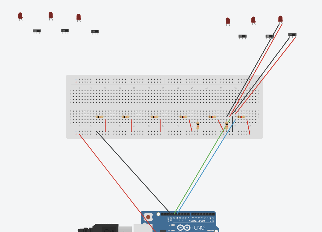
i see 2 resistors connected to your gronud bus in the photo, but have not idea what they are connected to. Are those resistors brown brown black, 11 Ohms?
Just a thought: those round sleeved Dupont wires aren't the kind that come with the Elegoo all in one set, are they?
I ask because I have found those round shank ones (I don't know what the plastic bit before the pin is called, @LarryD can you help me out? What are those called?) anyway, the round ones are ess-double hockey sticks eye tee.
I see you have some good quality Dupont wires with a snug fit, I'd get a pack of those good ones and like me, throw out all the roundy ones.
I draw one connection now, but the rest is connected the same way with a 220 ohm resistor.
I used this code to test every switch/connection. If I connect one cable set to the breadboard it works fine, but when I add a second connection things get mixed up.
void setup() {32
33  //start serial connection34
35  Serial.begin(9600);36
37  //configure pin 2 as an input and enable the internal pull-up resistor38
39  pinMode(2, INPUT_PULLUP);40
41  pinMode(13, OUTPUT);42
43}44
45void loop() {46
47  //read the pushbutton value into a variable48
49  int sensorVal = digitalRead(2);50
51  //print out the value of the pushbutton52
53  Serial.println(sensorVal);54
55  // Keep in mind the pull-up means the pushbutton's logic is inverted. It goes56
57  // HIGH when it's open, and LOW when it's pressed. Turn on pin 13 when the58
59  // button's pressed, and off when it's not:60
61  if (sensorVal == HIGH) {62
63    digitalWrite(13, LOW);64
65  } else {66
67    digitalWrite(13, HIGH);68
69  }70}
Why have you got a physical pullup resistor on the input pin when you use INPUT_PULLUP in pinMode() that turns on the built in pullup resistor for the pin ?
Your picture shows nothing connected to pin 2 of the Uno but you are testing its state. Why ?
Are you sure that you have connected to the correct pins of the switch and not to the normally closed and normally open pins instead of a connection to the common pin ?
How did you copy the code to paste it here ? I ask because something has happened to the line numbers
In my experience the easiest way to tidy up the code and add the code tags is as follows
Start by tidying up your code by using Tools/Auto Format in the IDE to make it easier to read. Then use Edit/Copy for Forum and paste what was copied in a new reply. Code tags will have been added to the code to make it easy to read in the forum thus making it easier to provide help.
So technically we can take out the first resistor going to every switch?
Yeah this was just a drawing (the software doesnt have the arduino giga), and I used this code as an example (I copied the code from the link from the arduino website).
I used the 22 en 23 port on my arduino and so on for every switch/button.
These switches im using now only have + and - to connect
You don't need the physical resistor and the internal one. Obviously the internal one is easier to use and involves less wiring. Note too that the sketch you posted test for an input pin state of HIGH which will be true when the switch is not closed
Those are odd markings for switch connections. Do the two switch connections make/break when you operate the switch ?
As to your diagram and sketch, it would be helpful if they matched and reflected your actual project
No, you must have some wiring issue. Repeating the pattern for additional switches and LEDs should be as straight ahead as you'd think.
Here's your test. I understand you are using other pins. I would avoid pin 13 on the UNO, even if it should work fine, as it does have some circuitry on it that can have undesired effects. Besides, it's 13.
void setup() {
  //start serial connection
  Serial.begin(9600);

  //configure pin 2 as an input and enable the internal pull-up resistor38
  pinMode(2, INPUT_PULLUP);

  pinMode(13, OUTPUT);
}

void loop() {
  //read the pushbutton value into a variable
  int sensorVal = digitalRead(2);

  //print out the value of the pushbutton
  Serial.println(sensorVal);

  // Keep in mind the pull-up means the pushbutton's logic is inverted. It goes
  // HIGH when it's open, and LOW when it's pressed. Turn on pin 13 when the
  // button's pressed, and off when it's not:

  if (sensorVal == HIGH) {
    digitalWrite(13, LOW);
  } else {
    digitalWrite(13, HIGH);
  }
}
Here it is with a few other changes; no one cares, but this is the only fully correct way to do the same thing:
void setup() {
  //start serial connection
  Serial.begin(9600);

  //configure pin 2 as an input and enable the internal pull-up resistor38
  pinMode(2, INPUT_PULLUP);

  pinMode(13, OUTPUT);
}

void loop() {
  //read the pushbutton value into a variable
  bool sensorVal = digitalRead(2) == HIGH;

  //print out the value of the pushbutton
  Serial.println(sensorVal ? "HIGH" : "LOW");

  // Keep in mind the pull-up means the pushbutton's logic is inverted. It goes
  // HIGH when it's open, and LOW when it's pressed. Turn on pin 13 when the
  // button's pressed, and off when it's not:

  if (sensorVal) {
    digitalWrite(13, LOW);
  } else {
    digitalWrite(13, HIGH);
  }

// or
// digitalWrite(13, sensorValue ? "HIGH" : "LOW");
}
For reasons.
Ppl sometimes use manifest constants to sort the HIGH/LOW pressed/not pressed lit/not lit stuff
# define PRESSED LOW
# define LED_ON HIGH

// and later

  bool sensorVal = digitalRead(2) == PRESSED;  // true if button is being pressed
That thing you are building? You are going to have to tell us more about it. Are the altimeter and current meter under control of the microprocessor?