Switching power with a DS3231 RTC module

The basic idea is to switch on the power to a microcontroller project periodically using the alarm function of a DS3231 which is running on its 3V coin cell. This could be useful in battery-powered projects where there are other devices such as sensors or SD cards that can't be put to sleep along with the processor. I just wanted to present some schematics showing how this could be set up.

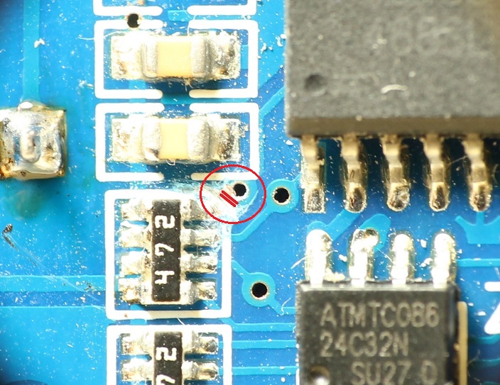
It's the INT/SQW pin of the RTC module that controls the power. And in all cases it's necessary to disconnect that pin from its pullup resistor on the module, which can be done by cutting a trace. The INT/SQW pin is an open drain output, which means it goes low when the alarm triggers, but is high impedance otherwise.

So the idea is that a low on that pin turns on a P-channel mosfet which supplies power to the project. The processor then does it's thing, then brings up Vcc to the module and configures a new alarm setting, and then, as its last act, clears the alarm flag, which releases INT/SQW and allows R1 to pull the gate back high, thus turning off the power.

The maximum voltage which can be applied at the INT/SQW pin is 5.5V. The first schematic shows a project which fits within that limit. In that case, the pin is connected directly to the mosfet gate, which has its own pullup resistor R1.

The second and third schematics were provided by Ian.M on the EEVblog forum, and add an intermediate transistor to deal with a 12V power supply. One uses an NPN transistor, and the other an N-channel mosfet. In both cases a wire has to be soldered to the positive terminal of the coin cell holder to provide 3V to the base/gate of the NPN/mosfet. The circuit is a bit odd, but allows a low on INT/SQW to turn on an NPN or N-channel part which normally would require a high voltage to turn on.

In the mosfet version there is a note that R2 probably is not needed. I breadboarded that circuit, and found it worked fine with or without R2. If R2 is eliminated, then power can remain on without any extra current flowing from the coin cell, which is a good thing. However, I am still uncertain why this works since the source of the mosfet is floating until the alarm is triggered. If any EE out there has a comment on why it works without R2, I'd like to hear it.

I hope these circuits will be useful.

Check your drawing or maybe I am missing something. You show the Gate connected to the power and the source connected to the output of the DS3231. I can see why it appears you do not need the resistor but is not a good design. I would connect the gate to the output of the DS3231 and the source to ground. for the transistor connect the base resistor to the DS3231 and the emitter to ground. Not critical but the high resistance (100K resistor) can cause funny problems. Unless you are counting on the gate capacitance as part of a RC network to slow things down I would lower it to preferable to less than 10K. The additional current will be supplied by the 12V system. My preference would be the mosfet/mosfet design no base current required long term.

Or you could just connect the INT/SQW on the DS3231 to an INT0/INT1 pin on the Arduino and have the Arduino go into Power Down Sleep mode. It's almost as good as complete power down

gilshultz:
Check your drawing or maybe I am missing something. You show the Gate connected to the power and the source connected to the output of the DS3231. I can see why it appears you do not need the resistor but is not a good design.

I think the design is correct. When INT/SQW goes low, the gate-source voltage goes to 3V and the mosfet turns on, which grounds the gate of the P-channel mosfet, and power turns on.

I would connect the gate to the output of the DS3231 and the source to ground. for the transistor connect the base resistor to the DS3231 and the emitter to ground.

That would make the polarity wrong. The gate or base needs to go high and the source or emitter low to turn on the mosfet, but the INT/SQW pin goes low when the alarm is triggered. So that doesn't work. I think the circuit works as drawn. It worked fine on my breadboard tests.

Not critical but the high resistance (100K resistor) can cause funny problems. Unless you are counting on the gate capacitance as part of a RC network to slow things down I would lower it to preferable to less than 10K. The additional current will be supplied by the 12V system. My preference would be the mosfet/mosfet design no base current required long term.

I'm not sure what you mean by "funny problems", but of course the user can select whatever resistor value they want. I breadboarded it with a 220K resistor, and it still worked fine, so I think 100K should work ok in most cases.

hzrnbgy:
Or you could just connect the INT/SQW on the DS3231 to an INT0/INT1 pin on the Arduino and have the Arduino go into Power Down Sleep mode. It's almost as good as complete power down

Yes, if it's just the processor that needs to shut down, putting it into sleep mode would certainly be easier. But as I said in the original post, if there are other modules involved that can't be put to sleep, cutting the power would be needed to maximize battery life.

I forgot to post a picture showing the trace to cut to disconnect the INT/SQW pin from the existing pullup resistor on the typical SD-042 module. That's required because that resistor is pulled up to the module's Vcc pin, but with the power off there's no voltage on Vcc, and that connection just messes up the circuit if left in place.

I should also have added that Vcc needs to be applied to the module only when you want to communicate with it over I2C (because SCL and SDA are also pulled up to Vcc). At all other times it can run off the coin cell at about 1.25uA, at which rate it will typically last a couple years.

libraries used:

Wemos D1 is powered ON every minute and sends a message to Telegram.

Original DS3231 board consumes 1.5mA of current. After both resistor blocks (pullups) and eeprom chip were removed, current is 100uA.

wemosD1asLoadAlarmTelegramMessage.ino (4.51 KB)

So is this working? I think you posted yesterday, then deleted the post. It appeared the problem with that version was the third line of setup() which cleared the alarm, which also turned off the power. It seemed it should have worked if that line was deleted. But I see you've picked a new library.

With regard to the 100uA, remember that if you have the CR2032 coin cell installed, you only need to power up the RTC when you need to communicate with it over I2C. Even if it is powered down, the coin cell will keep the clock going, and the INT alarm pin will still work. So you can save the 100uA if you just power the RTC Vcc pin from an Arduino GPIO pin, or from the Arduino's Vcc pin.

I think you posted yesterday, then deleted the post. It appeared the problem with that version was the third line of setup() which cleared the alarm, which also turned off the power.

I wish you had left that reply before i deleted my post, it would have saved me a couple of gray hair.

The DS3231 now has been modified according to the following blog: https://thecavepearlproject.org/read-the-blog/

It now runs from its 2032 battery only and draws around 2 or 3 uA during sleep (my multimeter isnt great), which is in accordance with the information found on page3 of the DS3231M datasheet.

The code needed to be updated for it to work in these conditions.

wemosD1TelegramOnAlarmDS3231VBatOnly.ino (3.95 KB)

FranciscoB:
I wish you had left that reply before i deleted my post, it would have saved me a couple of gray hair.

The DS3231 now has been modified according to the following blog: READ ➤ the Blog | Underwater Arduino Data Loggers

It now runs from its 2032 battery only and draws around 2 or 3 uA during sleep (my multimeter isnt great), which is in accordance with the information found on page3 of the DS3231M datasheet.

The code needed to be updated for it to work in these conditions.

I downloaded your sketch and looked it over, but when I came back to reply, your post had disappeared. But running on only the Vbat pin is certainly the way to keep the power usage down.

This topic was automatically closed 120 days after the last reply. New replies are no longer allowed.